
As many know the main difference between EJ20G ECUs and ours is the switch from 4 channel coil on plug to 2 channel wasted spark coil packs. I'm trying to get a 4 channel ECU to drive a 2 channel ignition.
Please forgive and correct my very basic, and very new, knowledge of electronics.
From the trouble shooting section of our FSM it looks like the ecu fires the ignitor by grounding the ignition pins. The pins are held high by pull up resistors and dropped to 0 volts when the output transistors are energized. When this happens the ignitor transistors switch state and the coil discharges.
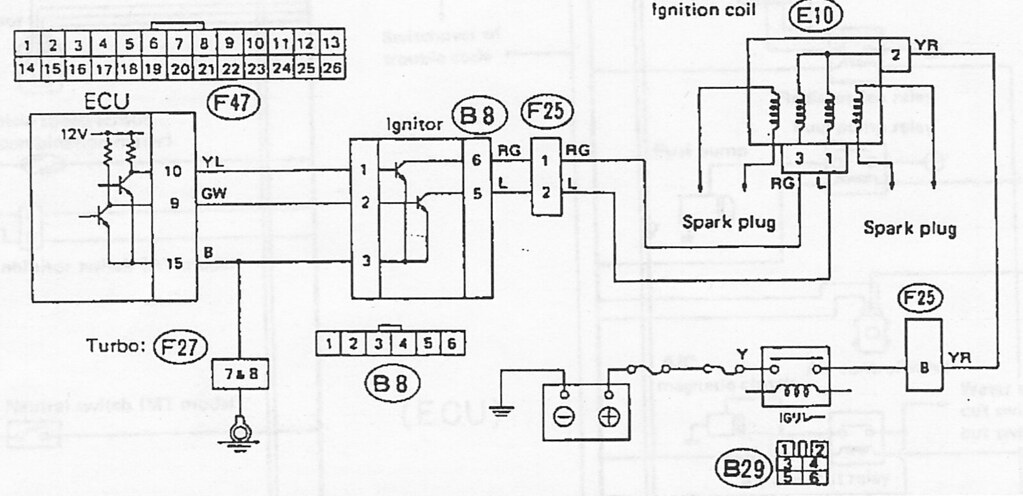
The following picture is from the EJ20G 4 channel setup. There is no showing of the ECUs insides but it's safe to assume it follows the same pull-up resistor, transistor forcing it low. It appears to be the exact same set-up as the EJ22t, just with double the channels.

Now here is where I need some help. I'm pretty sure you cannot just bond two ECU output pins together as this may damage one channel as the other fires? What I'm thinking might be possible is to isolate the outputs with diodes(?) before joining them together. Something like this...

Thoughts? Can it be this simple? What am I missing? If it really can be done similier to this I would then research diodes to figure out what kind.
