The wiring diagram picture, in this first post only, is wrong!
Pins 10 and 7 on the ECU need to be switched.
As promised, even if a bit late.
This is the procedure I used to install a 4 channel ecu into a USDM Legacy SS. This has been tested with both a BC5 EJ20G ECU and with a EJ20G Apexi Power FC aftermarket ECU.
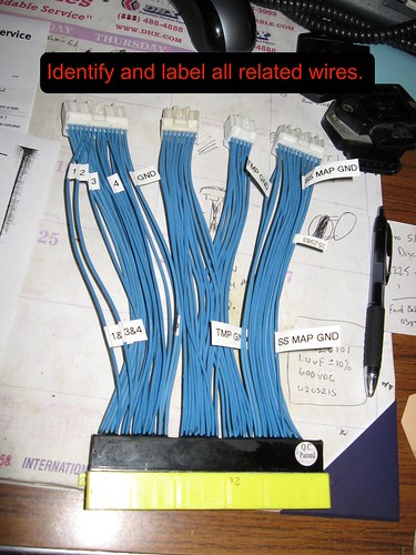
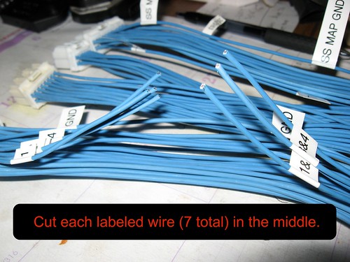
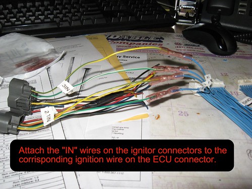
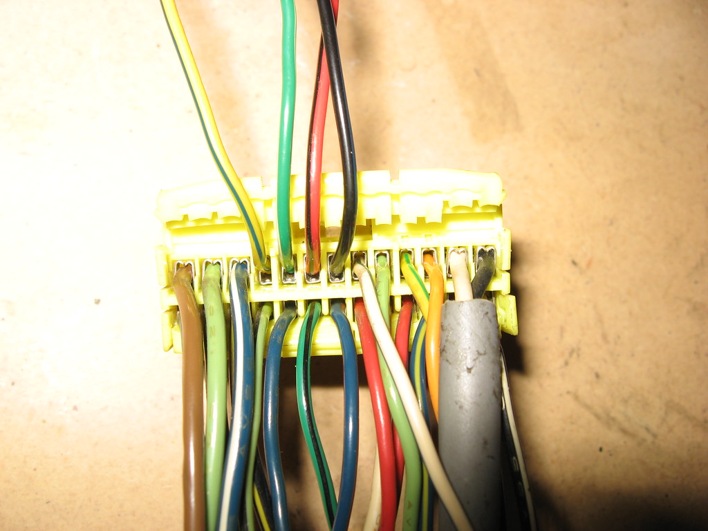
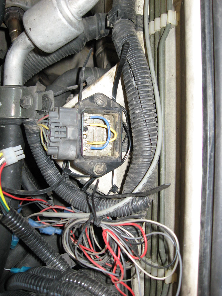
First you will need to add 2 pins to the 26 pin factory ECU connector (F47). The 4 wires going up in the pictures are the ignition outputs. The black wire on the right is pin #1 and the brown wire on the left is pin #13. The two factory channels are the Green/white @pin 9 and the Yellow/blue @pin 10. You will need to add the two wires located @pin 7 and 8. (I chose red/black and black). These wires will need to be harvested from a spare harness/ECU connector.
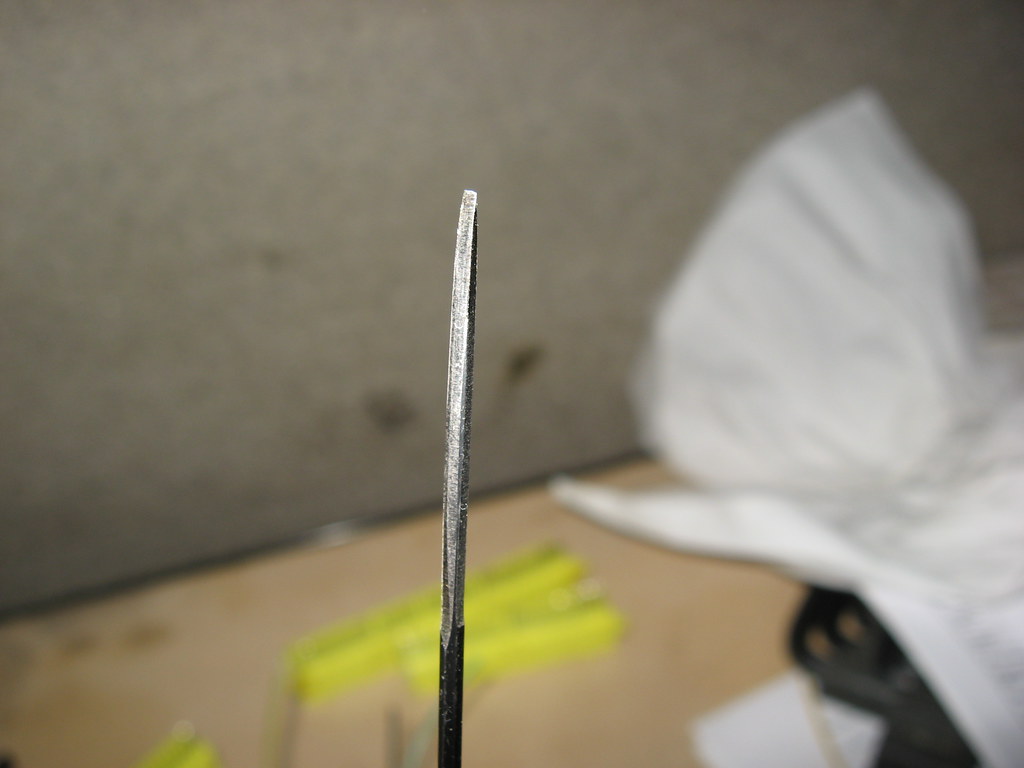
This is the tool I made to extract pins from the connectors. It's just an allen wrench ground to shape.
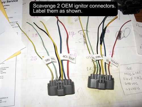
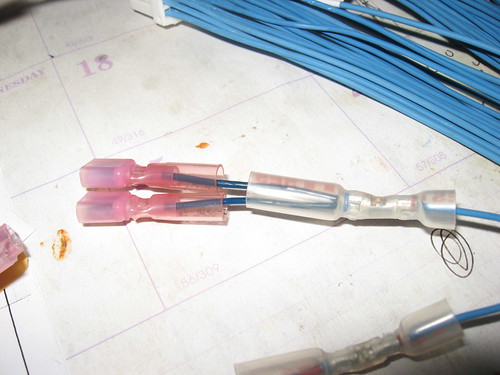
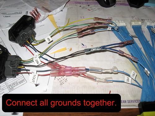
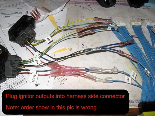
Once you have added the needed wires to your connector you need to add the igniter. I chose to use a SVX igniter. A JDM WRX or tandem factory Legacy igniters will work just as well. Follow the following diagram to wire them in. Basically each output from the ECU gets it's own igniter channel. After the igniter you can bond cylinders 1&2 and 3&4 together. Remember to ground your igniter/s.

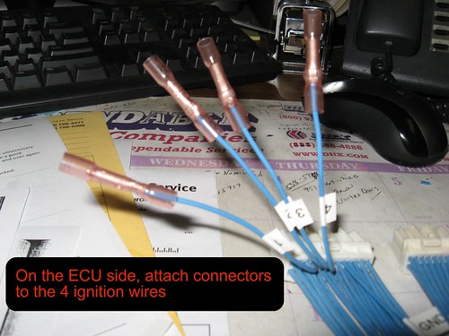
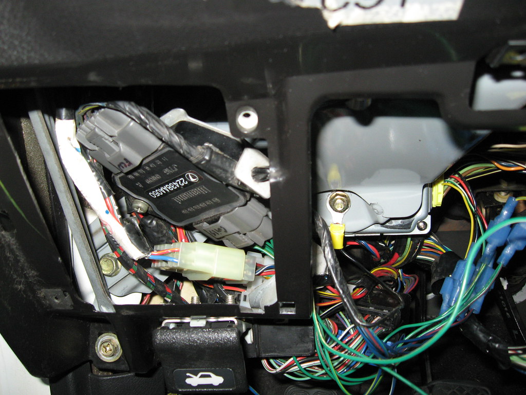
I chose to do this all inside the car right at the ECU location. I also used a jumper harness to avoid and permanent harness modifications. In this picture you can see 4 channels coming out of the ECU, but only 2 channels returning to the harness.
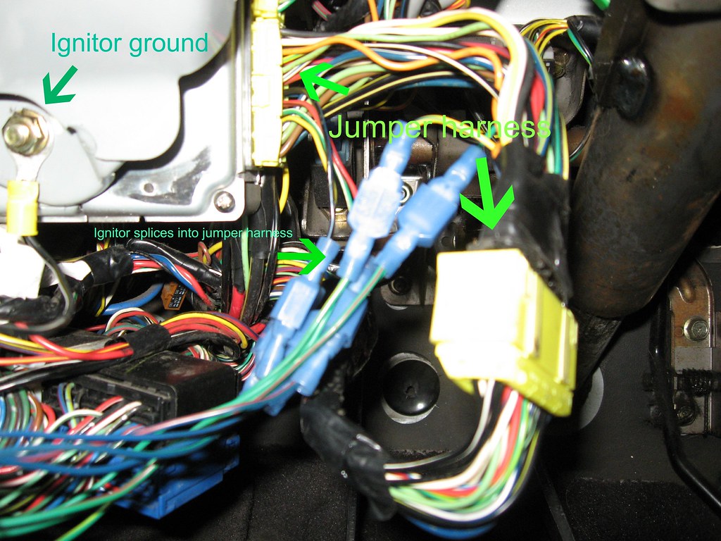
Igniter location. Just stuffed up there in this picture.
Now that you have added new igniters to the circuit, you need to remove the factory igniter. You can go under the hood and either splice (or jumper) it out. I chose to keep with my no-permanent-mods theme and gutted a factory igniter. Solder the inputs to the outputs and you've made a reversible jumper.
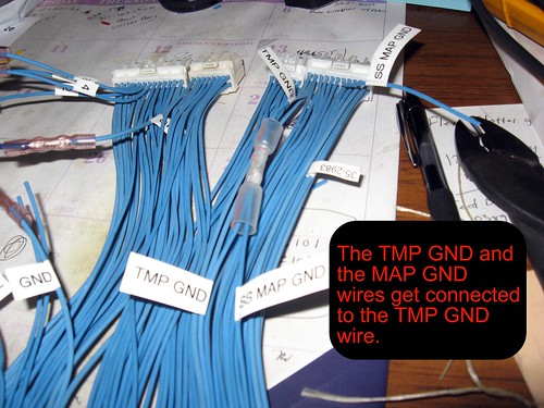
This is pretty much all that needs to be done with the ignition. In fact the car should now run, but most likely throw a code. It turns out that the pressure sensor is wired slightly differently on our USDM cars. The solution is to remove pin 5 on B48 and join it with pin 21 on B48. This could easily be done with a conversion harness also, if desired. Sorry no pics of this step, but should be a no brainer if you've got this far.
That's it. The car should now run and be code free. The rest is all detail work. Mounting, wrapping and making it looks good. You will most likely decide to deviate slightly to make the conversion suit your needs exactly, but hopefully I've given everything to get it up and running.