
BACKGROUND
The EJ22T ignition system is a 2 channel "wasted spark" setup with an external coil pack and an external 2 channel igniter. The ECU sends out two alternating trigger signals to the igniter. Each signal causes the coil to fire on one of the two paired cylinders. The cylinders are paired to the coil such that the spark arrives on the compression of one and the exhaust stroke of the other. With a firing order of 1-3-2-4, the cylinders that are 180 deg out of phase would be Cyl1-Cyl2 and Cyl3-Cyl4.
The EJ20G setup is for is a four channel coil on plug (COP). There are four coils each of which are molded to the sparkplug boots are physically located in the spark plug wells. Each coil has two wires, +B and the output of the igniter. Each coil pack is grounded through the mounting bolts to the head. There is a 4-channel external igniter that outputs to the individual coils and also takes as input four trigger signals from the ECU.
To boil it down, the EJ20G ECU will send out four igniter triggers, each trigger is sent 360deg apart when the EJ22T igner is expecting two 180deg apart. It is not possible to simply plug the EJ20G ECU into the EJ22t harness and expect the ignition system to just work.
The job of the 4to2 converter is to take as input the 4ch triggers from the EJ20G ECU and to output the equivalent EJ22T ECU 2ch signals to the stock igniter and coilpack.
INSTALLATION
Installation is pretty straight forward. Use this connector pinout as reference. The color of the circle represents the color of the wire from the converter box.
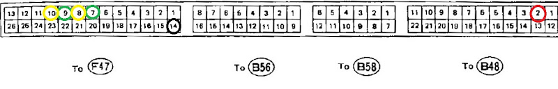
1) De-pin the original two wires that go to the igniter. These are on connector F47.10 (yellow-green) and F47.9 (green-white)
2) Insert the pre-pinned wires from the converter; F47.10 (yellow), F47.9 (green), F47.8 (yellow), F47.7 (green). The pinned yellow wires are interchangeable with each other as well are the pinned green wires with each other.
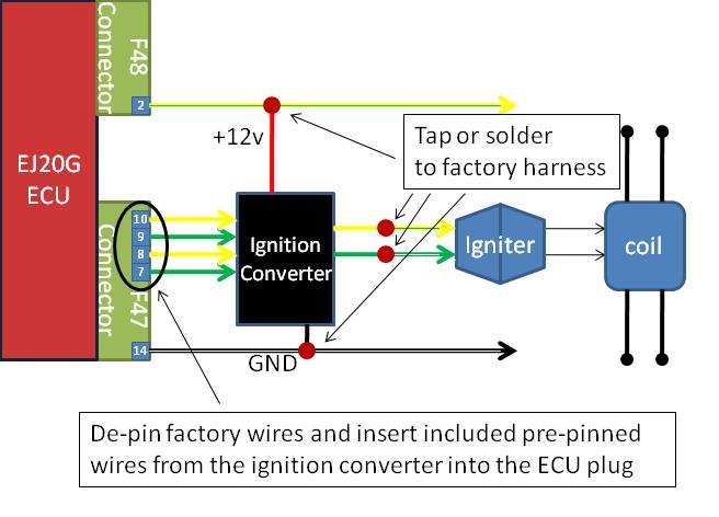
3) Tap or solder the non pinned yellow wire to the yellow-green wire removed from F47.10. Do the same for the green wire to the green-white wire depinned from F47.9
4) Tap or solder the black ground wire to F47.14 (black-white)
5) Tap or solder the red power wire to F48.2 (yellow-blue or yellow-red)
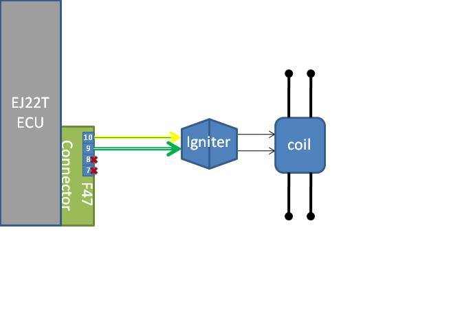
This picture represents the stock setup before adding the converter.
Here is what it will look with the ignition converter in place after adding the EJ20G ECU.
Here is a picture that shows all connections to the F47 plug. You can see in step 3 that I soldered directly to the pins of the factory wires.

CURRENT STATUS
6-24-11:
I fitted my first production unit on The Mule, and am happy to report it works just as well as the prototype. I pushed the boost up a bit and rung it out to 7k. It runs flawlessly.
At this point I am ready to take my first set of orders! I should have my first nine finished this weekend. Send me email direct on what you want and I will pass along paypal details.
rob . files @ gmail . com
6-15-11:
I handed off the test mule still running my prototype back to Drew for some unbiased opinions on how it runs. I'll let him elaborate if he likes, but the report was that as far as the ignition system goes, it runs as stock.
Ok, parts and PCBs came back last week. I worked on assembling the first one. I did miss one trace on the board, so the first batch will need a blue wire...damn. I am working on a small test bench in order to verify each one build actually works. I also need to pick up some more wire, then I think I will be ready to take orders; maybe as soon as next week. I have settled on prices;
Converter = $90 ($70 for those already running my tune)
Converter + Tune = $350
Converter + EJ20G ECU + Tune = $455
Shipping in the US is inclusive.
After the first one is finished, I'll post a pic.
6-5-11:
I got some road testing in this weekend with the converter and the EJ20G ECU on Drew's car. I installed a watered down version of my tune (max boost @12psi) as there is no boost gauge yet. Short story is that it runs fantastic. This bitch is done! I have sent the PCBs out for fab and have parts ordered. Once I get the final BOM figured out and an idea how difficult it is going to be assemble with all of these surface mount parts I will have pricing info.
5-23-11:After yet another complete circuit re-design, I am happy to report my prototype is up and running. I don't want to jump the gun and call it done until I get some good road miles first, but all looks solid. It starts, idles and revs perfectly on both the EJ22T stock ECU and the EJ20G ECU. Once I am satisfied after driving it I will finish up my PCB design and order parts for production.
4-20-11 I finally figured out why the proto wasn't working correctly wired into the car. It was a tough nut to crack. Basically what it comes down to is that I didn't properly characterize the signals used between the ECU and igniter and made assumptions based on my experience with Toyota parts. Once I figured out why the chip wasn't behaving correctly, I dug out the O-scope and verified, which I should have done first thing! It is an example of sloppy engineering; bad on me! I need to add a couple electrical components and it should be good. Parts are on order and will be able to pick up testing in a few days. I also found the correct source for ECU connector crimp terminals. This will greatly simplify installation.
4-11-11 More progress on the testing, but the proto is not done yet. I tinkered around on the bench and solved a few issues. Now it's back on the car, but still not behaving nicely. No matter how hard it tries, the car still won't run on 2 cylinders... The fun debug continues.
4-4-11: I am happy to report that I now have Drew's Franken-mule back in the garage for on car testing! I attempted to hook up the prototype and ran into my first issue. In an attempt to simplify installation I purchased a bunch of compatible ECU plug terminals. The theory being one would simply de-pin the stock wires and re-pin with my converter. Pretty slick eh? Well it turns out that even though the terminals are really really close, they just don't fit right. Ballz. I will have to rethink how to handle that. In the meantime, I worked around that and attempted to run the stock ECU with the converter. I recently modified the design to allow for it to work with either the stock ECU or EJ20G ecu without having to change the wiring. Feeling proud of myself and acting a bit too smartzy, I skipped the bench test after the change figuring it would work out of the box. Well.....not so smartzy after all. Car doesn't like it so much, so it's now back on the bench it goes
2-10-11: I am bench testing design #3 (I think its #3...I am starting to lose track
-Rob

