Page 3 of 6
Posted: Fri May 02, 2008 2:20 pm
by Legacy777
Yeah, I hear you. I guess it's one of those things that could happen in theory....but I'm not too sure how realistic it is.
Posted: Wed May 28, 2008 10:43 pm
by 93forestpearl
Bump for news?
Posted: Thu May 29, 2008 6:02 pm
by Legacy777
No real updates yet. The project is waiting for the intercooler radiator project to be completed. However the radiator project is taking up a lot more time...just trying to source & get a damn radiator that works. I think I found a place. They'll make me a custom one, but there's a 3-4 week lead time. I've emailed him and called him.....but haven't received confirmation that I'm in the que.
I've got the parts ready for the EM. I need to pull the ECU connector off an old ECU. I did some initial testing of the stock wiring harness to make sure it was good. I found that the wiring seemed good, however there was differences in ground, mainly between the engine ground and battery ground point, so I probably will add/redo some of the grounding to try and get that working.
It sucks, because I'd like to get working on this....but don't want to be rushed, and am hesitent to do the intercooler radiator upgrade & EM at the same time. I'd like to at least drive the car with the new radiator to make sure it's working fine.
Posted: Mon Jul 07, 2008 2:27 am
by 93forestpearl
Bump
I'm gonna keep harassing you about this

Posted: Mon Jul 07, 2008 3:38 am
by Legacy777
I know.....and you should.
I gotta get the radiator in first. I'm hoping I will get most of it done next weekend. I've been in Alabama most of all last week, and am back until Wednesday. I was going to work on things last Saturday, but I think I got a mild case of food poisoning or something. I'm going to take this Friday off to work on the car. It's my birthday, and the company has gotten their time out of me this past two weeks

Posted: Mon Jul 07, 2008 3:56 am
by 93forestpearl
Fair enough. I know what a lack of time is like when you have a project list about a mile long. This weekend I'm gonna swap diffs, play musical coilovers in back, change out both rear wheel bearings, and then breathe. Luckily I have an extra set of rear knuckles with one having the bearing already out, so I don't have to fight with the Hub-Tamer for too long.
Posted: Thu Nov 13, 2008 7:42 am
by bmxpunk
bump for updates?
Posted: Fri Nov 14, 2008 8:54 pm
by Legacy777
None as of now. I'm planning to pull the intake manifold this weekend and either prep the manifold for tapping, or tap it.
I can not seem to find any freaking NPTF taps locally. It super sucks.
Posted: Mon Nov 24, 2008 7:10 pm
by Legacy777
I finally got around to doing some work this weekend.
Good news & bad news.
Good news is I got the intake manifold off so I can tap it for the IAT sensor & additional tap for MAP sensor. It was a complete pain in the ass. I was dreading doing that....and it sucked about as much as I figured it would. I'm not looking forward at trying to shoe horn all that crap back together.
Bad news is I tried getting the connector off an old ECU to use for my "plug & play" harness, and the pins just broke off pretty easily. "Desoldering" didn't really work. I tried a dremel, and it broke a couple pins off. My only other thought is to use a torch to try and melt the solder enough to pull the pins out.....but I'm not sure that's going to really work either.
So I'm kind of back to square one with how to hook up the ECU. My other thought would be to repin all the stock ECU connectors so they match where they need to go on the Link.
I'll take any suggestions anyone has.
Here's pics
http://www.main.experiencetherave.com/s ... nkinstall/
Posted: Mon Nov 24, 2008 9:11 pm
by 93forestpearl
I've been thinking about that now too since I'm going to re-wire in the next shell I get.
What was your plan once you desoldered it? Solder the wires to the pins?
I have a couple old ECU's laying around, and I could use a tortch to get it out cleanly.
It would be really nice if we could find connectors for the ECU side that would take normal crimp-type pin connectors to go into the female ends.
I did just find this: A new ECU side connector. It's 38 pounds though.
http://www.m-cal.com/Products/MC04-3690 ... --(Yellow)
Posted: Mon Nov 24, 2008 9:28 pm
by Adam West
Wow that's heavy for a pinout! <grin>
Posted: Mon Nov 24, 2008 10:54 pm
by PhyrraM
This one if rom Road Race Engineering, but I believe others can be had cheaper. A bit steep, but considering how much you've already got into your EM......
Posted: Tue Nov 25, 2008 9:31 am
by 93forestpearl
I think I'll have to give Road/Race a call. If they want a reasonable amount for the ECU header, I'll think about it. From what Ive found, the old 4 plug yellow subau header is the same as the mitsu's of that vintage.
Posted: Tue Nov 25, 2008 7:06 pm
by PhyrraM
I *think* it's the V7 and V8 EVOs that share our connectors.
The one from Road/Race is about $160, but I seem to remember finding an "import" for about $100.
Posted: Tue Nov 25, 2008 7:11 pm
by Legacy777
Yeah I was just going to solder the back of the pins to the wires.
In doing a little research and now with seeing it first hand, those pin outs on the back side of the ECU connector are by no means sturdy in any way. With my past experience on the connector Vikash made and the cam trigger being finicky.....I'm cautious about undo stress on those pins. Vikash said to use an epoxy of some kind to seal everything up. This would provide the pins some additional support.
However if I could find anything else, I'd almost prefer to go that route. I'm very tempted to try repinning the stock ECU connectors.
I'll let ya know if I find anything else and what I decide to do.
Posted: Tue Nov 25, 2008 9:17 pm
by 93forestpearl
I could make a box to put the original piece in and support it with the screw holes that are already in it, but having wires soldered to those thin pins makes me nervous with fatigue stress over time. The expoxy idea Vikash had is a good one. I do also wonder about interference in the triggers. When I wired it the first time, I had to leave about two inches of the trigger wires without shielding all the way around. THe shielding was connected, but just not wrapped in that spot. It worked fine for over a year and a half. I think engine bay interference may be more of the issue that under the dash, but I don't know for sure.
Is that $160 what Road/Race gets for just the header, or for a complete plug-in jobby? They will not be able to make me a plug-in harness, so I would only want the header to build from.
What do you mean by repinning the stock ECU connectors?
If we were bulding race cars, this would be so much easier. Strip the thing and go Prodrive style on it.

Posted: Tue Nov 25, 2008 10:14 pm
by PhyrraM
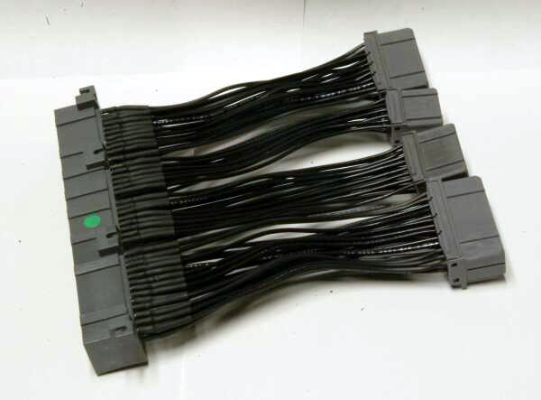
$160 for what is in the picture, it's from thier site. I assume you would snip and intercept any needed signals and leave the other ones alone as a sort of pass-thru. They sell it as a aid to piggyback intallation. It looks like they have done at least a *bit* of strain relief.
If I was to go that route, I would probably epoxy up to the end of the shrinkwrap. That would make it heavy, but almost bulletproof.
Posted: Tue Nov 25, 2008 10:27 pm
by 93forestpearl
I'm just wondering if what they sell is any different than the factory ECU header and if it is any beefier. I mau take one of the two extras I have and try the epoxy thing. I'll have to make a small form and possibly cover it with enough epoxy so the whole solid pin is supported.
This has the wheels turning, for sure.
Posted: Tue Nov 25, 2008 10:34 pm
by PhyrraM
From the looks of the pictures, I'm sure that the companies producing these jumper harnesses are just buying the PCboard connectors, trimming them down and soldering on wires. Basically the same thing we would do. They just have the tools to do a 'professional' job of it. I would guess that RRE doesn't even manufacture thiers. I'm sure it's a resale product.
I've made one from a harvested connector, and for $100 I'd buy the next one. $160?....not sure.
Posted: Tue Nov 25, 2008 10:52 pm
by 93forestpearl
I think I might just try to make my own. I *think* I left myself about two feet, maybe even three feet of wire on the original Link harness. I'm crossing my fingers on this one, heh. I'd like to find a little more realistic spot for the ECU this time, since the factory location is a PITA. Having the ECU plugs accessible is nice for adding stuff and unplugging it if I want to weld on the car. This may not be necessary but it gives me piece of mind.
Posted: Wed Nov 26, 2008 7:43 pm
by Legacy777
93forestpearl wrote:I could make a box to put the original piece in and support it with the screw holes that are already in it, but having wires soldered to those thin pins makes me nervous with fatigue stress over time. The expoxy idea Vikash had is a good one. I do also wonder about interference in the triggers. When I wired it the first time, I had to leave about two inches of the trigger wires without shielding all the way around. THe shielding was connected, but just not wrapped in that spot. It worked fine for over a year and a half. I think engine bay interference may be more of the issue that under the dash, but I don't know for sure.
What do you mean by repinning the stock ECU connectors?
Here's the stuff Vikash was talking about. It's a silicone.
"The silicone potting compound I used was E6000 adhesive. It's almost the same thing as Automotive Goop, so you could probably use that too. "
Regarding the shielding, I'm not sure it's really a big deal. The factory harness doesn't have shielding the last little bit.
What I'm talking about repinning the stock connectors.
The ECU plugs for the 1st gen legacy are the same style as the Link G3, and assuming G2. So what I was thinking of doing was just moving the pins around on the stock connectors to match the Link ECU, and then all I have to do is plug the stock male ECU connectors into the Link. I would probably have to do some additional wiring to tie the sensor grounds together, but it should be relatively straight forward.
What I like about that approach is I don't have a solder joint that will fail. With the last ECU adapter I used with the perfect power I ended up finding out that the cam or crank lead had a slight bit of resistance to it. It varied depending on how the wire was bent. I think that caused me some issues. I don't want to have to deal with that again.
Posted: Sat Nov 29, 2008 8:31 pm
by 93forestpearl
I guess I never even noticed that they may be the same. When I get my dash out I'll have to take a look-see. If I could do some re-pinning that would terrific.
Posted: Sun Nov 30, 2008 5:20 am
by Legacy777
Ran into some more issues.
I was doing wiring "check outs" to verify sensor wires. The crank & cam sensor wiring was about the only two sets of wires that were completely 0 ohms (100% continuity). Most of the wiring would trickle between 0.0 & 0.1 ohms. That may not be a big deal, but on a sensor that you're using for precise measurement, it can lead to variability and issues.
I may put together a list of what sensor wire readings I got, and the ranges I measured and decide whether I want to run new wiring for selected sensors, or new wiring for everything.
Plus, on top of that, I discovered the insulation was cracked on the harness wire for the knock sensor. At the break the wire appears to be in tact, but I can not get any continuity out of at the connector pin or at the break. So either it's fubared or there is another break some place, and I gave the wire out of a spare turbo legacy harness to Larry for his same
problem. So now I got to find another one.
http://bbs.legacycentral.org/viewtopic.php?t=38156
The fun continues.
Posted: Tue Dec 02, 2008 2:37 am
by 93forestpearl
Is the knock sensor wire shielded? I cannot remember. If it is, you should be able to reuse some of your trigger wire that came with your Link harness.
My car had 200k on it when I did the swap, and I had no issues with it passing the trigger tests and running. Do you have access to a scope? You could look at the trigger and knock signals for noise.
Posted: Tue Dec 02, 2008 7:08 pm
by Legacy777
Yes the knock sensor wire is shielded.
I was thinking about this last night. I have the entire Link harness, and I believe the two knock sensor leads that come with the harness are shielded. I need to confirm that, but if that's the case, I'll just use that.
Now I just need to decide whether I'm going to try moving pins around at the stock ECU connectors, or make some form of adapter.
I don't have access to a scope. I'd really like to have one if I could find a cheap one, or a used one.