Page 4 of 4
Posted: Tue Apr 05, 2005 10:49 pm
by All_talk
vrg3 wrote:Hardy - I dunno... I thought the area behind the valve covers is supposed to be pretty much continuous with the area in the crankcase, isn't it? I mean, don't a lot of inline engines have their PCV stuff only on the valve cover, with no fittings on the block?
Yep, pretty much continuous, the extra outlets on the turbo system are to achieve sufficient flow at lower suction.
Wow, what a thread… so much to say and I’m such a slow typer.
To some extent we’re over thinking things, maybe I can help clarify a few points.
The PCV valve (as stated before) is both a check valve and a metering valve, look at the construction detail on the page linked earlier in this thread. It’s fully open under moderate vacuum, but as vacuum increases a pinnel is drawn back into a necked orifice, this controls the volume of air drawn into the intake. Under positive manifold pressure (boost) the PCV is closed.
When the PCV is closed the intake pipe is the suction source.
On the older Subaru engine (EA series) one of the valve covers is the “fresh air intake.” Flow goes into the crankcase through one valve cover and out through the other valve cover (and case vent on the turbo) to the PCV or intake pipe depending on manifold pressure. This appears to be true of the N/A EJ22 (valve covers are intake and case vent is outlet), but it looks like the turbo EJ may use the valve covers as the outlet under low vac/boost (I’d have to get a good look at one to be sure).
The less effective evacuation under high load is typically not an issue on a N/A streetcar that rarely sees extended full throttle operation. But on a turbo car, sustained low vacuum or partial boost is much more likely so the system uses the intake pipe as the suction source often in normal operation. To achieve the same flow with a lower vacuum source the turbo vent system needs to be more open and interconnected.
Catch can location should be between the crankcase outlet(s) and the vacuum source. A single can could be used if both suction sources were routed to the can. The suction line for the intake pipe will be the one with the “venturi” end at the turbo inlet. So for the turbo car it looks like you may have two case outlets and two suction sources to route to the catch can. Or use two cans.
Open/closed deck has no effect on the PCV system.
Gary
Posted: Wed Apr 06, 2005 2:45 am
by THAWA
Vikash, you're right. These engines have the most complicated PCV system I've ever seen. But what other reason would there be for the two heads to be connected to the block in the middle? It just seems to me that under some condition there wont be enough flow going through the block and heads so the extra hoses are there to reroute it.
All_Talk, good ish

Posted: Wed Apr 06, 2005 3:01 am
by vrg3
All_talk - The EJ turbo and non-turbo setups are functionally identical except for the fact that the turbos have an extra tee connecting an extra fitting on the block to extra fittings on the valve covers. The non-turbo one does also use the intake piping as a source of vacuum at high load.
There isn't an extra crankcase outlet; the extra fitting connects just to the valve covers.
Hardy - Yeah, we agree. All I can think of is that closed-deck motors somehow have a "less free" path between the two areas.
Posted: Wed Apr 06, 2005 4:56 pm
by All_talk
vrg3 wrote:All_talk - The EJ turbo and non-turbo setups are functionally identical except for the fact that the turbos have an extra tee connecting an extra fitting on the block to extra fittings on the valve covers. The non-turbo one does also use the intake piping as a source of vacuum at high load.
There isn't an extra crankcase outlet; the extra fitting connects just to the valve covers.
I took a close look at the diagrams, I see what you mean.
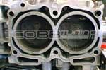
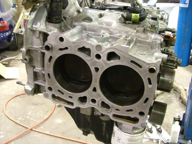
I don’t think there is any inherent difference in the head to case flow area between the open and closed deck blocks, here are some pics, EJ22T and EJ25.
I think the connection between the case and heads is just a balance tube to move vapors from the case to the heads, here’s my thinking, see if it makes sense…
The turbo engine is likely to produce more blow-by and spend more time in the closed PCV condition than the N/A. The blow-by vapors move passed the rings into the crankcase. Though the “special” fitting in the intake boot creates a lower pressure than the connection from the valve covers, both of these connections are at low pressure (vac) compared to a pressurized crankcase. I suspect that at high RPM/high boost that the case pressure can exceed the pressure at both intake boot fittings (especially in a engine with some mileage on it) and vapor flows out of the valve covers as well as the case vent. If these vapors were forced to travel to the valve covers through the passages in the head there flow would be opposing the flow of oil returning form the valvetrain (at high RPM there would be quite a bit of oil). This situation could not only cause vapor flow problems, but would also tend to hold more oil in the valve covers where it could be sucked into the intake. The balance pipe preserves the free flow of both blow-by vapors and return oil at high crankcase pressures.
Sound logic… yay or nay?
Gary
Posted: Wed Apr 06, 2005 5:02 pm
by vrg3
Hmm, so you're saying you think that the system is designed to sometimes flow crankcase fumes out of the fittings on the valve covers? Cuz the way I see it the fittings on the valve covers are just inlets for fresh air from the intake pipe.
Posted: Wed Apr 06, 2005 6:01 pm
by All_talk
Yes, I think it could be.
I guess the question is whether the engines production of blow-by vapors ever exceeds the volume that the case vent can extract through the intake pipe port with the PCV closed (assuming the rings aren’t completely shot). We know that both ports into the intake pipe are at some level of vacuum, if the suction from the case vent can’t keep the case pressure below the level at the valve covers connection to the intake pipe the flow will reverse. A little testing with a differential low pressure gauge would tell the tail. But the fact that the balance pipe exists and the diagram shows it flowing from the case to the covers supports the idea.
Gary
Posted: Wed Apr 06, 2005 6:49 pm
by All_talk
Just had another thought that might tell us something… do the “inlet” ports on the valve covers have oil baffles? If so, this might indicate they are expected to flow vapor out under some conditions.
Gary
Posted: Wed Apr 06, 2005 7:18 pm
by vrg3
Hmm... I don't see how the presence of the "balance pipe" supports the idea that the system is ever supposed to flow out of the valve covers. But I can see what you're saying about how that might happen.
The path from the fitting on the crankcase to the venturi at the compressor inlet takes a short bit of 19mm ID hose, goes through a short plastic pipe that narrows down to 12mm OD, goes through a short piece of 12mm ID hose, and then into the venturi which starts with an OD of 12mm and has a partial vacuum being pulled on it at the end.
The path from the valve covers to the intake tubing involves two long pieces of 12mm ID hose which connect to a relatively long 12mm OD plastic pipe tee, which then connects to the intake tubing without a venturi.
So it seems that the first path ought to flow much more than the second path. And I would imagine that in stock form, all the stuff is designed so it'll all flow out the first path.
But maybe when you turn the boost up and start screwing with things you end up creating so much pressure in the crankcase that you end up throwing crankcase fumes out both ways.
Hmph. We just need to find affordable vacuum pumps that can evacuate the crankcase at all times. I was looking at some of the electric ones used on diesels or as auxiliary pumps for some European spark-ignition cars, but I'm not confident they can move enough gas.
Hella makes this pump used on certain Swedish models that is specced to bring a 40 cubic inch container down to 15 inHg in 20 seconds.
I would say 15 inHg is probably too low a pressure, but still, that spec doesn't seem to me like it would handle the quantity of blowby a turbocharged engine would produce at full boost at redline. Like, say cylinder leakdown is 4%, and 2% of that is through the rings. Doesn't that mean 2% of what goes into the cylinder ends up into the crankcase? But that's such a huge amount. With a stock EJ22T, that could be like 150 cubic inches per second of pressurized air/fuel mixture, right?
Posted: Wed Apr 06, 2005 7:19 pm
by vrg3
Oh, just saw your other post -- I don't know if there are baffles. But baffles might be in place just to keep any particulate matter that may happen to make its way in there away from the rockers or something, right?
Posted: Wed Apr 06, 2005 8:25 pm
by All_talk
Yeah, without some testing or inside info from Subaru, it’s all a bit speculative.
My gut feeling is that in stock form and new (little blow-by), the valve covers rarely if ever see out flow. But with some mileage on the engine I think it’s pretty likely. My EA82T in my ’87 RX has a similar PCV system and I know it pushes some oil out of the “inlet” valvecover, I can see it looking down the intake pipe. But it’s got 293,000 miles on it and I flog it pretty hard at times.
Boxer engines always seem to have PCV oil/vapor control issues, just ask the air-cooled Vee Wee guys. I think it’s mainly due to the horizontal oil drain back from the heads, which slows down flow and the lack of vertical height between the crank (and associated windage) and the outlets. There’s just a lot more oil in the vapors close to the suction than in a L or V style engine. I guess its the price to pay for the lower center of gravity.
Gary
Posted: Sat Jun 04, 2005 3:07 am
by THAWA
Okay, so let's try to think some more about this.
EJ20G has no middle T
EJ205 has no middle T
EJ22T has middle T
EJ255 has middle T
EJ257 has middle T
It can't be something specific to US cars as the EJ205 doesn't have the T.
It can't be something specific to close deck engines as the EJ20G doesn't have the T.
Could it be related to the size of the engine?
Posted: Sun Jun 05, 2005 3:56 am
by vrg3
I suppose it could be... but it seems to me that the engine's output would matter more than its displacement.
It could be something about the head design, too.
Are we 100% sure the EJ20G doesn't have that piece?
Is the EJ255 semi-closed-deck like the EJ257, or is it open deck like the EJ205?
Posted: Sun Jun 05, 2005 7:14 am
by THAWA
Well yeah the power would make sense if the EJ22T didn't have it.
I suppose it could also have something to do with the heads, but what? IT can't be a DOHC/SOHC thing as we know both variants have it.
We are definately 100% sure!

Infact, Liberty RS's don't have as many fittings in the turbo inlet boot.
And yes they're semi-closed
Posted: Mon Jun 27, 2005 6:53 pm
by THAWA
Okay, throw that out of the window.
puckaveli wrote:I read your post on Nabisco.
The turbo legacy and 22b share the same block, but the 22b didn't get the squirters. The legacy blocks with the squiters should have 2 crankcase breather tubes and the 22b has only 1. This is from Adam at Lateral Performance, he specializes in 22b's and is a moderator on 22b.com forums.
So let's do another compilation
EJ20G no middle T
EJ205 no middle T
EJ22G no middle T
EJ22T middle T
EJ257 middle T
EJ255 middle T
So, it can't be specific to the type of engine deck, the type of heads, the engine size, the country, or the power output. I'm stumped.
Posted: Mon Jun 27, 2005 8:06 pm
by vrg3
Maybe it is engine size, but 2.2 liters is kind of in the middle?

Posted: Tue Jan 26, 2010 6:17 am
by RJ93SS
SUPERBUMP
Now i wonder how well this would work.?
http://forums.nasioc.com/forums/showthr ... ?t=1916975
great info btw
if the oil cap was vented, i wonder when it would see pressure and when it would see vacuum? probably at the same level the valve cover breather hoses would.
it would be nice to have a seperate vacuum source because the gases are hot and oil is lowering our octane levels, i wonder how all of this is tied in with the maf. if your sucking air out the crankcase than it wouldn't be measured by the maf, does the cpu compensate for this?
Posted: Tue Jan 26, 2010 5:43 pm
by brweber352
I believe the air in the crankcase is metered, It should come from the valve covers which are attached to the hoses that go to the weird looking T that attaches to the turbo inlet. I believe these are the fresh air inlets for the crankcase which is why i think you would have problems using breathers on these inlets because it would not be metered then. Plus the majority of the gases are from blowby which is initialy metered before the combustion process. I'm not sure how much oxygen is left after combustion. The more I think about our PCV sytem the more I don't want to touch anything, just add a couple catch cans and keep it simple.
I could be wrong, but I think this is how it works.
Brian
Posted: Tue Jan 26, 2010 8:04 pm
by entirelyturbo
I believe Josh has said the ECU contains a MAP/barometric pressure sensor, so maybe that monitors blowby.
Posted: Tue Jan 26, 2010 11:20 pm
by Legacy777
The ECU barometric sensor is purely for atmospheric condition changes.
Posted: Tue Jan 26, 2010 11:31 pm
by entirelyturbo
That raises an interesting question then: how does blowby get metered? It all enters the intake system after the MAF.
Perhaps the ECU has an algorithm of some sort that accounts for blowby at a certain RPM or throttle input?
Otherwise, I would think that would be extra air and it would run lean.
Then again, that may be what the O2 sensor's for.
Posted: Wed Jan 27, 2010 7:37 am
by RJ93SS
and if you were to modify the system, what changes are you going to see to the air fuel ratio's?
or maybe it is such a small amount that we dont notice it.
i also found that some jaguars actually come with a catch can
Posted: Wed Jan 27, 2010 8:47 am
by slowjoe
DerFahrer:
the extra air from the blowby should already have fuel mixed in because it is blowby.
Posted: Wed Jan 27, 2010 8:36 pm
by RJ93SS
slowjoe wrote:DerFahrer:
the extra air from the blowby should already have fuel mixed in because it is blowby.
good thought, and mix in some oil, i wonder what octane level blow by is?