Page 4 of 19
Posted: Tue Feb 15, 2005 1:48 am
by NICO
well i was having the same problem dont give up i solved my and the car is so fast, i need bigger brakes.
what i did was change the throttle sensor a little and the sensors that is on the bottom of the throttle bring them up a little and that will help out with stumbling, AND YOU MUST CHANGE THE BOOST that was the main thing i run 19psi stright out every gear.
the only thing done to the ecu is its bin chipped and when i put the factory chip back in it gets bad, BUT CHANGE THE BOOST and you will be ok.
for boost i am running a turbo smart boost controller and what i had to do was set it up way diffrent then before.
there is to types off boost one that gives you boost hard and fast and there is soft and long what you need when you are running the sti injectors is the soft and long boost it kicks in slow and works its way to the top its like it runs with the rpms, as they go up the boost gos up.
Posted: Tue Feb 15, 2005 3:50 am
by free5ty1e
Vikash:
lol... I hear ya.
I'm still thinking though, our MAF sensor's range doesn't matter; as long as the ECU thinks its getting a valid reading then it should adjust the injector pulse widths accordingly. The ECU thinks its got stock injectors, and thinks the airflow is within range, but the actual airflow has the signal pegged - yet the injectors duty cycle can still be adjusted via the trim numbers that would just scale the airflow signal output.
I'd love to design an ECU but man that's a huge project. I would probably only have the time to work out a decent piggyback system. I mean I can read a MAP voltage no problem but then there's calculations to do in realtime (or large lookup tables to fill) and such.
I envisioned the table as being RPMs vs Throttle Position... is that what the S-AFC's table has?
Anyway I really don't think the limited range of the stock MAF sensor is an issue when rigging up something to fool the ECU into thinking it is in range, as long as both RPM and throttle position are the two axis on the table. I suppose the partial throttle drivability will directly be affected by the resolution of the table, but I've got 16k of flash memory to work with for lookup tables - shouldn't be a problem.
The result can of course be displayed as a digital readout of the o2 sensor voltage along with the current position in the table. I bet it wouldn't be a problem to catch super-rich or super-lean points in the table and let you review them after a run, so you know where to begin adjusting the trims. I bet I could even do an auto-tune mode where you make a run and the trims are calculated along the way - or at least progressively bumped towards the right direction. Might have to make a few runs but it should be able to learn if things work out the way I'm thinking they will...
By the way - thanks for debating this with me V-man, two heads are better than one. Once we've ironed out exactly what the chip need to do I'll code the hell out of that biatch and start experimenting on my car. I'll send you a chip to play with too once I've got something testable.
Posted: Tue Feb 15, 2005 3:55 am
by vrg3
No problem, I'm enjoying this discussion.
You're right that you can cover most of the possible range of injector duty cycles using the entire range of possible fake airflow inputs, but you do need to know what's actually happening. The problem with indexing by RPM and throttle position is that you can have vastly different airflows at any given RPM and throttle position when you have a turbo.
But why not just index by RPM and MAP? Airflow at any given RPM and MAP depends only on VE, ambient air pressure, and MAT. VE would be read out of a user-tunable lookup table, and you could either just assume values of MAT and ambient pressure, or try to collect some of that information somehow.
That's pretty much what piggybacks like the UTEC and e-Manage do. I'm pretty sure that's how the UNICHIP works too.
Posted: Tue Feb 15, 2005 4:01 am
by free5ty1e
Hmm... that's not a bad idea. MAP would be a more useful signal than TPS, although perhaps there could be a few different TPS ranges which each have their own tables (or adjustable scale factors, at least).
Bear with me though, as I'm about to ask some shocking questions that expose my extreme acronym ignorance (EAI) - what's VE, and what's MAT? I think I'm understanding your idea but not fully yet

e-Manage, huh? That's supposed to be a good one...sweet
Posted: Tue Feb 15, 2005 4:05 am
by vrg3
I'm happy to explain any TLAs. VE is volumetric efficiency. MAT is manifold absolute temperature.
You should give the MegaSquirt MegaManual a read, especially this chapter:
http://www.megasquirt.info/manual/mfuel.htm
Well, keep in mind that all three piggybacks I just mentioned also have some means of controlling ignition timing. Whenever you screw with the airflow signal you screw with both fuel and spark.
Posted: Tue Feb 15, 2005 4:31 am
by free5ty1e
Hadn't thought of that... it would affect timing wouldn't it? I'll check the MS manual out, that'll probably clear up a few things - thanks.
Anyway, isn't MAT one of the measurements the ECU monitors with a sensor somewheres? Maybe an AIT sensor? To tell you the truth, I've never checked for either so I'm again exposing more of my ignorance lol
So VE would be another table that the user could adjust through the interface, thats no problem.
When compensating in this fashion for oversize injectors, what typically has to happen to the ignition timing to correct it? Advance it, or retard it? (What's the ECU try to do when we lower the MAF signal to get a good injector pulse width?)
Posted: Tue Feb 15, 2005 4:36 am
by vrg3
Our ECU doesn't have an IAT sensor. MAF-based engine management doesn't need it. You could install one though.
Generally when load is lower, timing is more advanced. So if you make the ECU think there's less airflow than there really is, you'll get more advance. Somewhat unpredictably more, since the ECU has a fair bit of leeway in adjusting timing.
Posted: Tue Feb 15, 2005 4:40 am
by free5ty1e
gotcha. OK so there should also be a timing adjustment table for how much to retard the spark at any given point on the main table? Maybe the main table needs to be more than two dimensional, which is also possible.
Now for the kicker - never had to adjust timing before, hadn't even gotten that far along in the modification process in any vehicle I've had previously. In our cars, how would you think I could achieve this with this chip we're discussing? No idea how to even start on this one
Posted: Tue Feb 15, 2005 5:02 am
by vrg3
Nah, two-dimensional is fine. Index by MAP and RPM. Have two tables, one for airflow adjustment and one for timing retard.
Timing retard wouldn't be that hard if you did it ghetto-style.
Quick overview of the ignition system:
The ECU's ignition outputs are driven by NPN transistors in an open-collector configuration with pullup resistors to the +12v rail. They drive the bases of the NPN power transistors in the ignitor. When the transistor in the ignitor is active, it closes the ground side of the coil. When this circuit is opened the spark plug fires.
So you could basically intercept the low-current signal between the ECU and the ignitor. Use a digital input to read it and drive it with your own open collector transistor with a pullup to 12 volts. On a rising edge, raise the output. On a falling edge, start a timer and when the timer times out lower the output.
The length of the delay can actually just be read straight out of the timing retard table. Sure, it might be nicer to be able to specify retard in terms of degrees rather than milliseconds, but it's functionally pretty much equivalent since the table is indexed by engine speed.
How's that sound?
Posted: Tue Feb 15, 2005 5:11 am
by free5ty1e
Dude. Sounds like some firmware to me. I can do that.....for an inexpensive device such as I plan for this to be, timing adjustments in ms or us will be fine just fine. I was a little worried about how I'd do that in degrees lol
But seriously that sounds completely doable now. I think I'll get started on routing the analog modules and laying the chip out this week, I bet I'll have some code to post soon.
So - d'ya happen to know if the RPM signal is handy anywhere as a voltage already? Or do I have to take the CPS pulses and time them to determine RPM?
I must remember to thank Megasquirt for their incredibly informative on-line manual! Thats way more detailed than I ever thought possible on a consumer product... gotta love when you actually get a breakdown of exactly how a product you just bought works!
Posted: Tue Feb 15, 2005 5:24 am
by vrg3
Yeah, it's fundamentally pretty simple.
Are these microcontrollers rated to industrial and/or military temperature ranges? Cuz the standard consumer range is 0 to 70 degrees Celsius.
That's the thing about MegaSquirt -- it's not a consumer product. It's a DIY project with its origins in a very grassroots effort.
The ECU's tachometer output pin supplies a 0v-12v square wave whose frequency is proportional to engine speed. I don't know whether it's one pulse per revolution or one pulse per spark or what, but you can figure that out.
Posted: Tue Feb 15, 2005 5:33 am
by free5ty1e
Gotcha. I'll just have to check out that signal with me 'scope and see what she looks like (and measures at idle!)
Was hoping there was a pin on the ECU that drives the tach gauge with a voltage - I suppose I'd have to rip the dash apart to get to that signal. Oh well, timing the tach pulses shouldn't be a problem either.
CPU operational speeds range from 98kHz to 24MHz - should be plenty of speed to perform the planned operations... power consumption is not an issue on this project so we will run at full speed.
They are usually rated to -40 to 85 degrees C, but they do indeed have automotive-rated silicon that can withstand 105 degrees C. That should be sufficient, I'd think. Besides, I don't envision the chip inside the engine compartment. It'd be on the circuitboard next to the LCD in the cab. Signals would be run to it through the firewall, I suppose. Driving a standard parallel LCD in the cab from the engine compartment might raise some timing issues from the length of the wires needed to connect it. They should be short to ensure reliable operation, I think.
What a nice world it'd be if well-supported, detailed, open units like the Megasquirt were considered consumer products! Thats a hell of a standard to compete with but that'd probably be a good thing. Oh well, too bad it's an unrealistic idea
Posted: Tue Feb 15, 2005 5:42 am
by free5ty1e
Oh - just to clarify,
Table 1 = RPM vs MAP, contains airflow trims
Table 2 = RPM vs MAP, contains timing retard trims?
or is table 2 going to have different axes?
Posted: Tue Feb 15, 2005 5:47 am
by vrg3
Yeah, 85 degrees should be fine if the device is in the passenger compartment. I would say the signal should be run to the ECU rather than through the firewall to the sensors.
I don't think computing power will be a problem at all... 98 kilohertz may be a bit low, but depending on the instruction set I would think even one or two megahertz would do. You'll probably want to use a crystal so timing can be precise. And it seems what you want is three digital input that drive interrupts for the tach signal and ignition inputs, two digital outputs for the ignition outputs, two ADCs for the MAP and MAF signals, a DAC for the mangled MAF signal, and whatever I/O stuff you need for the LCD (6 or 7 digital output lines for an HD44780 in 4-bit mode?) and configuration interface (RS232 and a laptop, I guess?). What do you think?
Oh, you might want to look at BG Micro (
bgmicro.com) for cheap backlit LCDs.
I think those two tables ought to just use the same axes. And for simplicity's sake, I'd say to just keep the axes fixed and regular. It's designed for our cars anyway, so a 16x16 MAP/RPM table going from maybe 3 psia to 30 psia and 500 RPM to 6500 RPM seems appropriate.
Hmm. Or it might actually be better to use a GM 3-bar MAP sensor instead of the stock one. It'd be an extra piece of hardware but then you wouldn't be limited by our stock MAP sensor's range.
Posted: Tue Feb 15, 2005 6:02 am
by free5ty1e
I'm actually trying to get this started right now... lol... I'm usually not working this late but you've got me thinking.
Yes you're right, any signals I can find in the engine compartment should be available on the ECU, and we've got pinouts for that in this board's wonderful repository of information. Woohoo! I'm organizing a good set of comments for the code and configuring the pinouts.
Anyways its the Intel instruction set, and I will definately use a crystal to maintain accurate timing (it needs it, the internal oscillator never comes calibrated right and that needs to be done on a chip-to-chip basis).
I'll check out BG Micro, for now I'll just use the 8x2 displays I have lying around, yep in 4-bit mode they take almost a whole port (7 pins). The tach input is a high-impedance pin routed to a timer module.
So - we have two ignition signals I need to read and delay? That shouldn't add any complexity... just another rising-edge interrupt, could use the same timer for the delay...
And are milliseconds a proper unit of time for measuring and delaying all of this? Probably microseconds, or hundredths of a millisecond, anyway. Just trying to determine what I should divide the system clock down to for a timebase clock for precise delays.
The GM 3-bar sensor's not a bad idea, I can just add a user option to select that later if it seems as though anyone with this chip intends to use one. I think the ranges we're discussing with the stock sensor will be sufficient for now.
Posted: Tue Feb 15, 2005 3:38 pm
by vrg3
Heheh... Cool. That's how I do a lot of cool work too.
Intel instruction set? Not, like, the 8086 instruction set, right?
Are the LCDs you have lying around backlit? Cuz in the end you definitely want backlit. But for testing it shouldn't matter.
The ignition signals would be on the ECU's ignition control pins. Two pins, like you said. If the microcontroller needs 5v signals instead of 12v, you could just put a 4.7v zener between the signal and ground. Like I said before, there's a pullup resistor inside the ECU so you won't be running too much current through the diode, and the ECU doesn't have any monitor circuits to check that its ignition signals are working so it won't get mad.
I think hundredths of a millisecond would probably be appropriate. Let's see. 6500 RPM is 108.333 rotations per second. That's 3900 degrees per second. So one degree is about 0.026 milliseconds.
Hmm. Maybe microseconds would be better.
The tuning interface can actually take its input in degrees and convert them into units of time before saving the table to flash memory.
If you have a spare ADC in the end, it would (in my opinion) be very useful to also monitor coolant temperature and display it. The LCD in normal use could then operate as a coolant temperature gauge and boost gauge. Those are the two gauges I most wish our cars had come with from the factory.
And if you have a spare digital output and a spare ADC, it might also be cool to do boost control. Have an 8x8 table indexed by TPS and RPM whose elements specify a duty cycle for the boost control solenoid. You can leave the complexities of tuning that table up to the user; it's certainly capable enough, as that's exactly how early WRX ECUs control boost.
And then you can also do stuff like limit boost when the engine's cold.
Hehe, another digital output could easily be for a shift light.
Mmm, feature creep prior to the construction of a prototype...
Posted: Tue Feb 15, 2005 4:07 pm
by mikec
Doesn't feature creep always happen with something as exciting as this Vikash?
Posted: Wed Feb 16, 2005 7:25 pm
by Legacy777
Very interesting thread....I know this is late...but wanted to make a comment on the flow profile and offsetting the MAF sensor.
The profile described/shown below is for laminar flow.
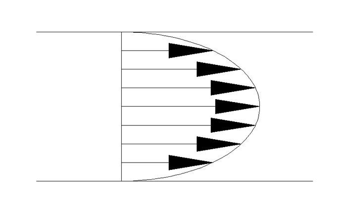
Due to the placement of the MAF sensor and the overall conditions/operations of how a automotive engine operates (not at any one point) the air flow profile is more then likely going to be mostly turbulent, or may have a small/initial formation of laminar flow in the center part of the flow's cross-sectional area.
Because of that....I don't thing offsetting the MAF would be the best of ideas.
Posted: Wed Feb 16, 2005 9:37 pm
by Innovative Tuning
This discussion makes me wonder if I'm maxxing the stock MAF on our rally car. We're leaning out over 12psi. We're maxxing something...the fuel system or the MAF. Perhaps I'll throw a multimeter on the MAF while boosting and have a look. Has anyone done this?
-Mike
Posted: Wed Feb 16, 2005 9:41 pm
by vrg3
What turbo are you using, Mike?
Posted: Wed Feb 16, 2005 10:11 pm
by Innovative Tuning
vrg3 wrote:What turbo are you using, Mike?
stock....the TINY one
Posted: Wed Feb 16, 2005 10:17 pm
by vrg3
You're almost certainly not hitting the MAF sensor's rail. If you're still using the stock fuel pump, though, it's possible that it's not flowing as much as it should.
Rather than hooking up a multimeter, you should build my scantool.

How much beyond 12 psi are you pushing the tiny stock turbo?
Posted: Wed Feb 16, 2005 10:52 pm
by free5ty1e
Feature creep = no problem. I'll just make a list and keep addin' em as I get pieces working. Boost control sounds like a great idea, its a natural for a product with this microcontroller in it. There are more than enouch digital and analog resources to do everything you hit there. I can just offer upgrade chips with newer firmware that will plug right in and you'll have new features. I was thinking too and later versions will have a serial laptop interface, that shouldn't be too hard to write.
I'd like a first version to just monitor a bunch of crap and I can begin working out the conversions and offsets - I want to see the MAF voltage, MAP voltage, and coolant temp voltage on an LCD in my car and I can go from there. Then I'll add the tach pulse reading and add a button to switch between 1 pulse per revolution and 1 pulse per spark, and continue experimenting... this thing ought to come together quite nicely.
The LCDs I have are not backlit, I agree the product should have a backlit display - I'll keep my eyes out but probably just cross that bridge when I come to it. The ones I have will be fine for development, I can test things in the daytime
Oh and I second you building VRG's scan tool. It's a damn handy thing to have!
Posted: Wed Feb 16, 2005 10:54 pm
by vrg3
Cool. Yeah, it might actually be nontrivial to find an appropriate LCD in the end. A lot of them have EL backlights that require inverters and can't easily be dimmed with a rheostat.
Let me dig up the transfer functions for the sensors for you, so you can have it display useful units rather than just volts.
Posted: Wed Feb 16, 2005 10:56 pm
by free5ty1e
word. I figured volts would be a good first place to start, then adding the transfer functions (or appropriate lookup tables) would be an excellent next step. That's right, you've got all that crap - you wrote a scan tool that outputs useful measurements dincha? heh