Page 1 of 1
Trying to bypass OEM radio fader, need electrical Gurus!
Posted: Sun Jul 08, 2012 7:48 am
by afterthisnap
The left side sound cut out on the oem 1990 tape/aux head unit. Jiggling the fader control worked for a while to restore full sound, but now the left side is totally dead.
The front/back fade setting works fine.
Treble/Bass seems to be functional.
I've read that you can bypass the fader/potentiometer by replacing it with resistors rated at half resistance of the fader/potentiometer.
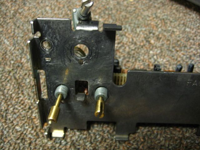
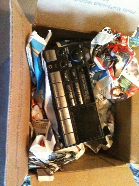
I opened up the unit and the fader connections are a bit more complex than I anticipated. Here are the pics:
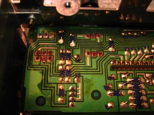
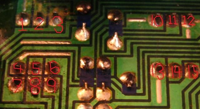
I think the FUBAR condition is in the 1,2,3 connections.
Checking resistance with all settings in the middle, I get
1-3: 45 ohms
1-2: infinite
2-3: 70 ohms
With the left/right fader turned all the way clockwise, I get
1-3: 45 ohms
1-2: 60 ohms
2-3: 5 ohms
With the left/right fader turned all the way counterclockwise I get
1-3: 45 ohms
1-2: 7 ohms
2-3: 55 ohms
I'm not entirely sure what to make of this, as when the fader is turned full counterclockwise (right volume cutout), I don't get any sound from the left speakers. I don't get any sound from the left speakers in any setting anymore.
I know it's easy enough to put in an aftermarket unit, but this is a quest of curiosity to see if I can rig a fix.
I don't need fade/balance, so I thought perhaps 2 20 ohm resistors from 2-1 and 2-3 would bypass the fader and give me full left/right sound again. Please let me know if I'm missing something as circuitry is not exactly my forte.
Thanks.
Re: Trying to bypass OEM radio fader, need electrical Gurus!
Posted: Sun Jul 08, 2012 9:17 am
by afterthisnap
Apparently I don't know how to use a multimeter...
All these values were taken at a 10x setting. At 1000x I get different values but they are relatively the same.
Also, I get different values if I test the same connections but switch the black/red probe of the multimeter.
Re: Trying to bypass OEM radio fader, need electrical Gurus!
Posted: Sun Jul 08, 2012 11:47 am
by turboleg
Firstly, I just want to make sure we are using the same terminology:
Balance - controls left/right sound
Fade - controls front/rear sound
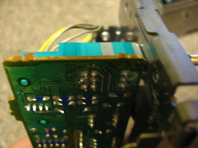
I haven't personally had one of these units apart, and its kind of hard for me to tell where the traces are going in the pictures. But if you feel you were able to achieve sound by jiggling the knob, I would start there. Check connection directly at the potentiomter leads. Through hole technology was a bit week in the automotive industry in the 80's and 90's. Heat/cold cycles could often break weak (cold) solder joints. Just do a close up (magnification helps) examination of the PCB and the connections. If you find cracked solder, reflow the solder with a solder iron. If there is no visible issue, I would suggest desoldering the potentiometer and checking the characteristics of the POT off board. There will be three connections per potentiomter elements. Often they are refered to as Pot+, Pot- and Wiper. Measurement between Pot+ and Pot- will never change. There should be some measurable resistance - this resistance is approximately the rated value of the potentiometer (so halving the value would give you complete balance). I would then suggest checking resistance between Pot+ and wiper (write down the max and min results) then measure resistance between Pot- and wiper (again write down the mas and min result and compare to Pot+ to wiper measurement). More than likely the pot should have a linear characteristic - for every 10 degrees of turn you will see an increase/decrease of 10 ohms for example. If there is a dead spot in the POT (infinite resistance) or if you suddenly see resistance values jumping around, you know the pot is bad.
More than likely you are seeing different values with the meter because there are diodes somewhere between the pot and the connectors you are measuring. Diodes, in general, only allow current to flow one direction. Since a resistance meter uses a small voltage/current signal to determine resistance value, it will be effected by a diode in a circuit. This is why I suggested removing the pot from the board directly. Electrical guys are trained to examine circuits on boarrd, but believe me, as you begin examing the circuit it turns into a cascading spiderweb. Eventually an "untrained" person could figure it out, but more than likely it would take a LOT more time. The other benefit of measureing the Pot off board is to determine if the Pot is even really the problem.
If you find that the POT is indeed the issue, you may have a few options, you could check the POT for a manufacturers part number. You may be able to find the exact replacement POT at one of the Electronic Big Wigs (digikey.com or mouser.com). This is probably unlikely, but worth a quick look. Alternatively, you would want to identify which terminal was which on the board. Check the toal resistance of the Pot+ and Pot- value I mentioned above, divide the value directly in half and place two resistors, one from Pot+ to wiper and the other from Pot- to wiper. This would essentially mimic the pot in the middle position. One fairly improtant item is the power rating of the resistors used. Be careful here! More than likely the power requirements are low, but you still need to be careful. For example if you were to use a .1W rated resistor where a 1W resistor was required, the resistor would litterally burn up under the power load.
If your really into doing this stuff, I'd suggest buying a Digital Multimeter with an autorange feature. I use a fairly expensive brand - Fluke Model 179, but it is truly overkill for what your working on. Try stopping by sears, radioshack, or pretty much and hardware store and find yourself a cheap digital meter. IIRC I was able to pick one up for around $15 for my brother to use in the garage. Autorange will help with the 10x 1000x settingn issue as the meter will autoscale.
Hope this helps and have FUN!
Re: Trying to bypass OEM radio fader, need electrical Gurus!
Posted: Mon Jul 09, 2012 2:42 am
by afterthisnap
Wow. That's a lot of help!
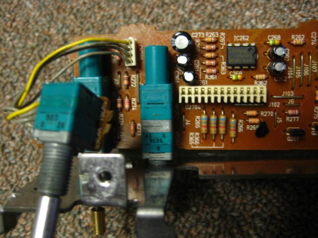
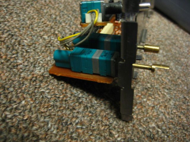
I'll take it apart further and show how the pot is installed to the board.
The balance and fade are on one knob and the pot includes connections 1 though 9.
Connections 10-15 are on the pot that controls treble/bass.
I did already reflow the solder previously to fix the aux jack (and AC unit), but the fader went out over a week or two and was directly affected by jiggling. Futher solder repairs to the pot connections didn't do anything. I'm pretty sure I've crunched up the insides of the pot pretty good (hence the want for the resistor fix). I've already looked for replacement pots and these seem to be pretty much impossible to get without ordering 800 or more units.
I have a nicer Craftsman digital multimeter but I think it is a dead unit as it won't take resistance (reads infinite for everything, even copper wire) after I left it baking in the front seat during 101 degree day. I'm going to get it replaced tomorrow so hopefully the pot will be out by then and I can take some accurate readings.
Thanks.
Re: Trying to bypass OEM radio fader, need electrical Gurus!
Posted: Mon Jul 09, 2012 6:20 am
by 91Beater
Do this...
(1)220--(2)--220(3)
You'll use two 220 ohm resistors to approximate 450 ohm
Do the same for 4-5-6 and 7-8-9 but using the same approximation I gave you above, but you'll need to use different resistors if the end-to-end values aren't the same. For example, if they read ~1,000 end to end, use a pair of 470s.
I spec'd 220, because that's a common off the shelf resistor value.
The two halves need to be exactly the same from the same batch
Re: Trying to bypass OEM radio fader, need electrical Gurus!
Posted: Mon Jul 09, 2012 6:21 am
by afterthisnap
Hey, 91. Is that assuming that I remove the pot alltogether?
Re: Trying to bypass OEM radio fader, need electrical Gurus!
Posted: Mon Jul 09, 2012 6:23 am
by 91Beater
afterthisnap wrote:Hey, 91. Is that assuming that I remove the pot alltogether?
Yes. I'm not sure how pots are held in place, but you can clip two out of three legs on each set and leave the side frame pins so that they physically remain in place for cosmetic reasons.
The board looks like a simple single layer PCB, so another option is to entirely leave the pot in place, but cut the traces that go to the pot, shave the coating on PCB to expose copper, then solder in SMD resistors. If you don't know what you're doing, I wouldn't though.
Another hack job I don't recommend is dousing the pot with MAF or electronic cleaner, then shoot some silicone spray. That will clean it out, but it won't stay fixed if the problem is due to worn carbon tracks.
Re: Trying to bypass OEM radio fader, need electrical Gurus!
Posted: Mon Jul 09, 2012 7:00 am
by afterthisnap
Re: Trying to bypass OEM radio fader, need electrical Gurus!
Posted: Mon Jul 09, 2012 7:21 am
by 91Beater
I'm guessing 1-2-3 is the balance
the other two are front-rear fader and one set is for left, other set for right but they turn at the same time.
That's a complex pot. I'd just bypass it using six resistors.
Re: Trying to bypass OEM radio fader, need electrical Gurus!
Posted: Mon Jul 09, 2012 7:12 pm
by afterthisnap
New fancy autorange multimeter says:
Middle Setting
1-3: 9.6 kOhms
1-2: 12.4 kOhms
2-3: 12.53 kOhms
Clockwise setting:
1-3: 9.6 kOhms
1-2: 9.61 kOhms
2-3: 9.3 Ohms (no kilo)
Counterclockwise:
9.6 kOhms
7.6 Ohms
9.62 kOhms
All these were taken with the pot on the board. I'm about to take it off now.
4-6: 10.2 kOhm
4-5: 13.6 kOhm
5-6: 13.6 KOhm
7-9 had identical values
Thanks.
Re: Trying to bypass OEM radio fader, need electrical Gurus!
Posted: Mon Jul 09, 2012 7:36 pm
by afterthisnap
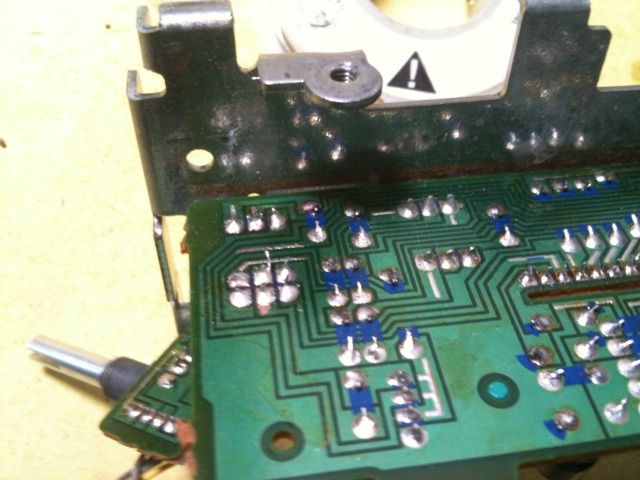
Desoldering pumps are cool!
Off the board I get:
Middle setting:
1-3: 39.7 kOhm
1-2: 19.9 kOhm
2-3: 20.0 kOhm
Clockwise:
1-3: 39.7 kOhms
1-2: 39.7 kOhms
2-3: 10.4 Ohms
Conterclockwise:
1-3: 39.7 kOhms
1-2: 7.7 Ohms
2-3: 39.7 kOhms
I'm wondering if the heating from desoldering did anything to normalize the middle setting. Regardless, I'm still into the idea of doing the bypass. It looks like the pot+/- resistance for 1-3, 4-6, and 7-9 are all about 40 kOhms.
Will six 20 KOhm resistors do the trick?
Re: Trying to bypass OEM radio fader, need electrical Gurus!
Posted: Mon Jul 09, 2012 7:45 pm
by afterthisnap
Hey, Turboleg.
I'm planning on putting in the highest wattage rating resistor I can find. I don't really know how I could measure wattage with all this outside the car.
Re: Trying to bypass OEM radio fader, need electrical Gurus!
Posted: Mon Jul 09, 2012 8:21 pm
by turboleg
Hi Afterthisnap. Potentiomters are, in general, very low wattage devices. A 1W pot is generally very pricy so circuit designers tend to compensate by stepping down through other areas of the circuit. It's never really a good idea from a circuit design stand point to design around a high current handling pot, because your essentially wasting energy as heat and therefore your design would be very inefficient. You can probably find 1W resistors in the value you need at radioshack or the like. Just be sure to check the physical size, in general as the wattage goes up the physical size increases as well. The actual method for determing what wattage resistor you need would be to meaure the voltage across the pot or the current through the pot and then calculating wattage Power= Resistance x I^2 or Power = V*I or Power = V^2/R : where V = Volts DC, I = Current DC. You would be able to determine if the wattage value was too low by virtue of the resistors becoming warm to the touch, but this is very subjective....so I hold tight to the higher wattage better comment.
As far as the resistance value is concerned it appears that you have 40K ohm pots, so you are correct that two 20K ohn resistors per pot would be the way to go.
The interesting thing is that you didn't have any wild values from the pot during measurement (at least that I can see). I would expect to see that in some position of the pot you would get a infinite or open condition.
Re: Trying to bypass OEM radio fader, need electrical Gurus!
Posted: Mon Jul 09, 2012 8:47 pm
by afterthisnap
The radioshack here in town is terrible! Six 20k resistors would have required buying 2 multipacks totaling $40.
I just ebayed 100 shipped for $2.50
Re: Trying to bypass OEM radio fader, need electrical Gurus!
Posted: Mon Jul 09, 2012 8:55 pm
by turboleg
That's a good price for 100 resistors.
Re: Trying to bypass OEM radio fader, need electrical Gurus!
Posted: Tue Jul 17, 2012 12:52 am
by 91Beater
for signal level pots, 1/4 or 1/8W or more than adequate.
Looks like the number I gave you originally were off, because you misread the analog meter.
You need to know which scale on the meter to read and multiply it by the correct ratio shown in the dial.
Re: Trying to bypass OEM radio fader, need electrical Gurus!
Posted: Wed Jul 18, 2012 11:34 am
by afterthisnap
Resistors came in- Pics to follow.
Re: Trying to bypass OEM radio fader, need electrical Gurus!
Posted: Fri Jul 20, 2012 1:53 am
by afterthisnap
I matched resistors with a multimeter and soldered them in.
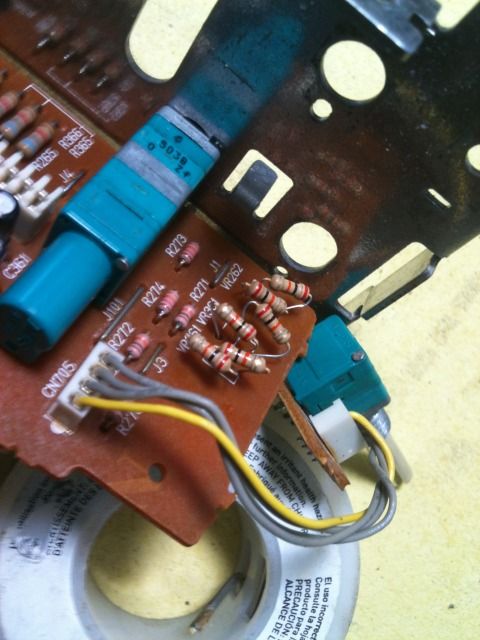
I put it all back together and plugged it in to have about 5 seconds of just passenger side sound, and then everything went dead.
Luckily, I also Ebayed a backup plan:
Everything sounds great from the Ipod.
I'm actually really surprised at how clean the sound is at high volume with the stock headunit, Ipod, and STI speakers.
Anyway, thanks for entertaining me as I tried my hand and circuitderping!