Page 1 of 1
Crank and Cam sensor + and - signal
Posted: Sat Jan 25, 2014 9:19 pm
by Mdmvisuals
Hey there,
Ive swapped a ej22t into my 1969 Karmann Ghia. I am running a Haltch Sprint 500 Stand alone ECU.
I need to find out which wire is what on the Crank and Cam sensors. I was told the Engine is a Reluctor type and not hall effect.
Would anyone be able to help me out with this info??
and the car...

any insight and tips would be greatly appreciated!
Thanks!
Re: Crank and Cam sensor + and - signal
Posted: Sun Jan 26, 2014 12:34 am
by mike-tracy
Very cool project!


Saw this guy at a vegas car show, talk about chrome, lol.
Anyways, I don't know the answer, but Legacy777 uploaded the full FSM right here, if you care to do some digging.
 http://bbs.legacycentral.org/viewtopic.php?f=12&t=14485
Re: Crank and Cam sensor + and - signal
Posted: Sun Jan 26, 2014 12:53 am
by Legacy777
Welcome to the BBS!
Looks like a fun project.
You were told correctly that the triggers are reluctor types.
Regarding the wiring for the crank & cam sensors, the wiring diagrams only give the color of the chassis wiring. Are you using the Subaru chassis wiring so you can see the wire color? If not, probably the best option is to try and match up the connector pins with the wiring diagrams. I think I may have an old crank & cam sensor, but I would need to try and dig it out to look at the connector.
Re: Crank and Cam sensor + and - signal
Posted: Sun Jan 26, 2014 9:52 pm
by Mdmvisuals
Thanks Legacy,
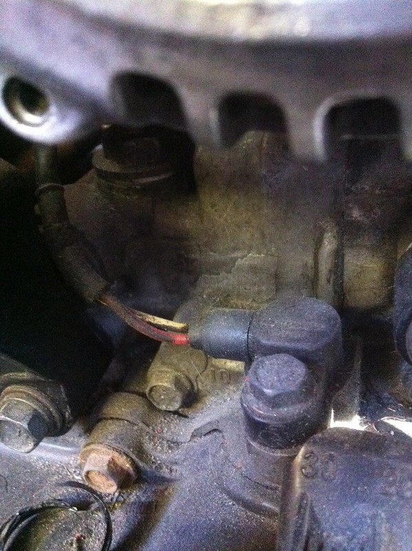
Heres the connectors before i did some splicing...
More so the connector in the back to the left... those are the wires off the chassis,
Black yellow and white.

Which can also be seen here again. Im also wondering which wire would be the signal ground for the coolant temp sensor?? is it the red or the black?

Thanks again
Re: Crank and Cam sensor + and - signal
Posted: Sun Jan 26, 2014 11:04 pm
by Legacy777
Ok, thanks for the pictures and wire colors. Here is the wiring layout
Crank Sensor
Black - Positive Signal
White - Negative Signal
Yellow - Shielding
Cam Sensor
White - Positive Signal
Black - Negative Signal
Yellow - Shielding
Re: Crank and Cam sensor + and - signal
Posted: Tue Jan 28, 2014 12:52 am
by Mdmvisuals
Thank you!
Would you know crank position trigger pattern for this engine?
Re: Crank and Cam sensor + and - signal
Posted: Wed Jan 29, 2014 12:03 am
by Legacy777
Do you have a set of options to select from? In my Link ECU software, the trigger mode is listed as "Subaru V1-6".
You can kind of see the teeth on the crank gear in some of these pics
http://www.main.experiencetherave.com/s ... eadwork/23
http://www.main.experiencetherave.com/s ... imingbelt/
This is a decent picture as well.
http://www.main.experiencetherave.com/s ... G_2092.JPG
Re: Crank and Cam sensor + and - signal
Posted: Thu Jan 30, 2014 8:59 pm
by Mdmvisuals
Legacy777 wrote:Do you have a set of options to select from? In my Link ECU software, the trigger mode is listed as "Subaru V1-6".
The Haltech has "Subaru PRE MY01" and "Subaru Later MY01" for options.
Its currently on the Pre MY01. It also has a "variable crank angle" under the Crank angle Degree option. What should the crank angle position be at, or is that variable thing ok to use?
I have spark. my fuel pump is working and there is fuel in the rails. But my injectors aren't injecting. There is 12V at the injector and everything is grounded. I don't know how other ecus work... but the when the haltech wants the trigger the injector it sends a ground signal and then it squirts... but its not doing that, I don't know why they aren't working. Is it possible that all 4 injectors could be pooched?
I check the ohms, the book I have says between 11 -12 ohms for the 90-94. Mine all said 13 ohms.
Re: Crank and Cam sensor + and - signal
Posted: Sat Feb 08, 2014 10:14 pm
by Legacy777
I would think the PRE MY01 setting would be correct.
I'm not sure exactly how the variable crank angle setting should be set. Does the manual give you any information on that?
Most if not all ECU's work by pulling the injector circuit to ground to actuate the injectors. Where are you grounding the ECU wires? Typically there will be multiple grounds, one for the ECU itself and then a separate for the injector drivers. I would recommend running those to a good ground sources. The factory sensors ground to the back of the intake manifold. I tied my ECU ground to that and ran a separate ground lead from the battery to that point as well.
The 13 ohms should be fine.