How to Repair a Leaking Steering rack: Subaru Legacy, '90-94
Moderators: Helpinators, Moderators
How to Repair a Leaking Steering rack: Subaru Legacy, '90-94
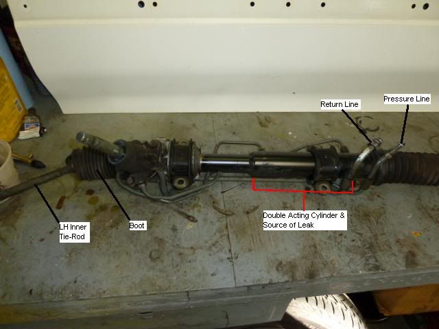
If your power steering reservoir runs low, then you have a leak. For older cars with rack and pinion steering, this is normally caused by a damaged passenger side (RH) rack seal. When the steering rack boot cracks, road dirt and sand can be carried into the rack seal as the rack slides back and forth with each turn of the vehicle. The RH seal is usually damaged first as it is nearest the boot area, while the LH is shielded by the length of the toothed rack. Repair requires refinishing the rod and replacing the rod seals. This can be done inexpensively and without special tools.
Why would you want to fix your own rack when a rebuilt is available for $160? Well, as Gump says, “you never know what you’re gonna get”. Racks are usually extremely worn out when they are sent to the core rebuilder. So, you may be receiving a rack in worse condition than the one you sent in. Yes, remanufacturers do grind the seal areas of the rack, but these may be ground grossly undersize. Furthermore, there is nothing they can do about worn pinion or rack teeth, at least not for $160. They will also use the cheapest seals, boots and tie-rods they can find. That means your gamble will be inferior to a repair using these instructions, OE seals and boots. Your cost to do it right the first time is: seal kit $40, boots $48, sandpaper $15….
Required Tools:
• 12mm socket and ratchet
• 14mm wrench
• 17mm wrench
• 19mm wrench
• Large Crescent wrench (30mm opening)
• Small flat-tipped screwdriver (1/8” wide)
• 1/8” punch
• Hammer (dead-blow preferred)
Required Materials:
• Kerosene
• Moly grease (STA-Lube Disc Brake Grease works well: http://www.crcindustries.com/auto/conte ... SL3161&S=N)
• One sheet each of 3M wet sandpaper in 400, 800, 1000 and 1200 grit: http://solutions.3m.com/wps/portal/3M/e ... 0CVBK1Q8gl
• Permanent marker
• 3/4” masking tape
• Razor blade
• Subaru output seal kit P/N 34128AA211, ’90-’94 Legacy
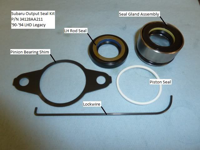
Shop Time:
This repair requires that you remove, tear-down, clean twice, refinish, reassebmle and then install a power steering rack. If I had all the parts on hand, I could easily do it in a weekend (8 hours). Plan accordingly, as your your ride could be down for a few days.
Alignment Preservation:
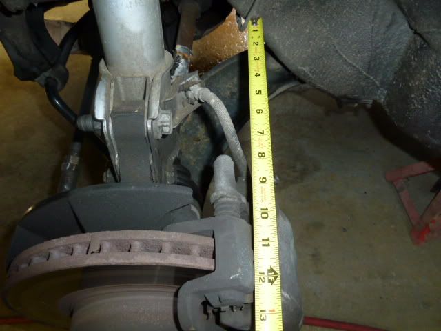
Straighten the steering wheel and let the steering lock in the nearest position. Remove the tires and record a measurement from the steering knuckle to the body. Try to keep this measurement parallel with the rack for accuracy and repeatability. This measurement will be used to align the steering wheel to the rack and pinion. Remove the rack from the car, complete with outer tie rod ends to preserve alignment. Take to car wash and steam clean. Try not to get water in the two open hydraulic pressure and return lines.
Inner Tie-Rod Removal:
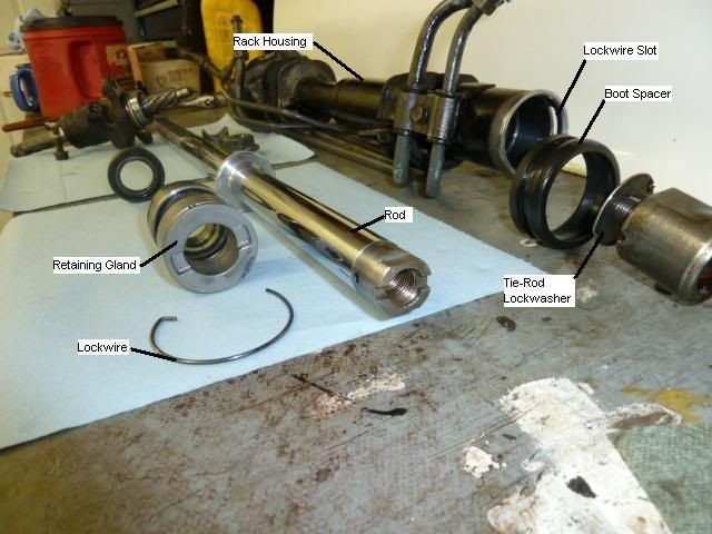
Flip up the large end of the rack boots, exposing a spring garter. Move the garter away from the rack housing and pull the boot free from the housing. To gain access to the inner tie rod connection, roll the boot back on itself, exposing the tie rod lock washer. Place a 19mm open end wrench onto the rack wrench flats, then hammer out the lock washer indentions using a small diameter punch. Place a large crescent wrench on the inner tie rod flats, and with the 19mm wrench against the bench top, hit the crescent wrench with a dead blow hammer knocking the tie rod threads loose. Note that all threads are RH threads “righty-tighty, lefty-loosey”. At this point, the tie-rod can be unscrewed by hand. Repeat process to remove opposite tie-rod.
Backlash Adjustment Sleeve Removal:
This sleeve presses the rack against the pinion teeth. Loosen the 30mm locknut with a big crescent and dead-blow hammer. Use a 14mm socket to remove the adjusting screw. Turn housing over and dump out the spring and adjustment sleeve.
Pinion Assembly Removal:
Before the rack can be removed, the drive gear or “pinion” has to come out. Loosen all four hydraulic lines from the input housing, and then remove the two pinion housing screws. With a few wiggles, the pinion assembly will pull straight out of the rack housing. Note the gasket between the pinion assembly and main housing. It is a shim used to set the depth between the pinion bearing and the rack housing and will be replaced with a new shim. The old shim can be removed using a razor-blade at a slight angle.
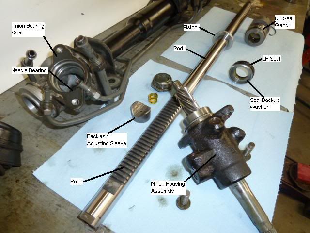
The pinion assembly will not be resealed as these seals usually don’t leak. The pinion, unlike the rack, experiences only rotational motion and is not subject to high contamination or heat. Clean the pinion teeth and ball bearing, and set the assembly aside.
Retaining Gland Removal:
The rack assembly is held together with a lockwire that is removed through a slot at one end of the housing. To remove the lockwire, first expose its end by turning the retaining gland. The gland turns easily using light taps against the lugs on its end. When the end of the wire is visible, lift using a small screwdriver, and then again turn the retaining gland. This will cause the wire to climb out of the slot and unwind from the housing. The last part of the wire is a 90 degree tang that fits into a hole in the gland. Just lift it straight out. A new lockwire is supplied in the repair kit.
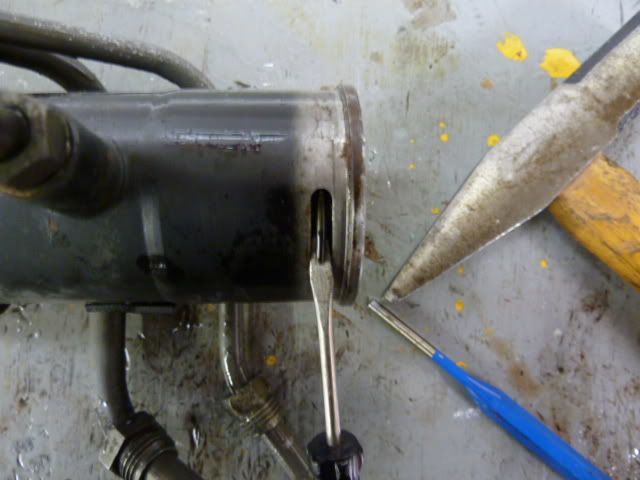
Rack/Rod Removal:
Pull and turn the rack at the same time, to help the teeth move past the LH seal. Be careful not to let the end of the rack drop down inside housing, as this could cause a scratch in the housing cylinder. With the components removed, you will probably find a portion of the seal gland to be rusty. A new one complete with seal and o-ring is supplied in the repair kit.
LH or Inner Seal Removal:
The inner seal is pressed in and will have to be tapped out. Stand the housing assembly on end, with the aluminum portion facing up. Next, insert a socket with a diameter just small enough to slide into the bore of the aluminum housing. Insert the handle of a half-inch drive breaker bar into the bore and against the socket, then tap on the end of the handle until the seal pops loose. Examine the parts that just came out. One will be a freeze plug looking thing called the seal backup washer. Its job is to prevent the seal bushing from popping out under hydraulic pressure. As such, the inner diameter is close tolerance to the OD of the rod.
Final Cleaning:
Take the housing back to the car wash and blast away any remaining grease. Note that there is a needle bearing in the pinion area. After washing, dry the water from the bearing using a paper towel, and apply a coat of moly grease to the needles. Then, carefully dry the cylinder bore using paper towels and a plastic or wooden handle to move the towels through the bore.
Pour some kerosene into a coffee can and clean up all the little parts, then blow dry with compressed air and set aside on a paper towel.
Parts Inspection:
Inspect the cylinder bore to make sure it is smooth with no dents or deep scratches. Shallow scratches won’t hurt anything. Sure, the piston slides and seals against the cylinder wall, but if it leaks from one side of the piston to the other, it just takes away some efficiency of the power assist. However, it will not cause a leak outside of the rack.
Check the inner diameter of the backup washer for burrs caused by the removal process. If any exist, these must be removed with a file or sandpaper. The ID is only .020” larger than the rod, so it has to be burr free.
Slop in the steering is caused by excessive wear of rack and pinion teeth. Since 90% of a steering wheel’s life is pointing straight ahead, tooth wear will only be found on the center of rack. Same thing for the pinion, only a couple of teeth will be heavily worn. The good news is that the pinion can be turned so that when reassembled, wear free pinion teeth are in contact with the worn part of the rack thereby reducing steering slop.
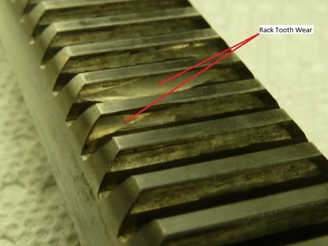
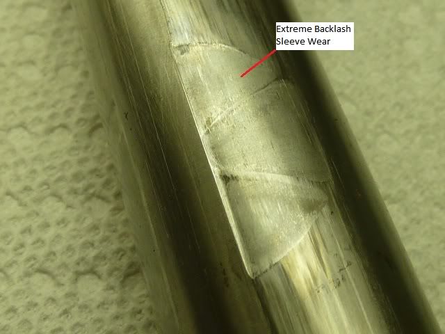
The rod portion of the rack is the most important. It should be inspected for radial erosion and linear scratches in between the piston and the vent holes. Also of concern is wear at the backlash adjustment sleeve contact point. This type of damage may be sanded out but must follow proper technique.
Rod Re-finishing:
This is imperative to eliminate leaks! The rod is to be re-finished using 3M wet sandpaper in grits: 400, 800, 1000, and 1200. If you are using full-sheets, cut these into thirds. If using half-sheets, cut in half. Begin by measuring the rod diameter using a caliper (it doesn’t need to be calibrated or accurate). Record this dimension as you will be comparing your final sanded diameter to make sure it is not too small or out-of-round. The seals should tolerate up to 0.003” of rod reduction and 0.001” of out-of-round, although I doubt anyone would take that much off using this home-brew method. Next, mark “1, 2, 3” equally spaced around each end of the rack. You will use these marks to index the rod 120 degrees in between sandings, thereby preventing an out-of-round condition.
Mix dishwashing soap and water in a large bowl. Find something low to sit on (I used a milk crate), then place a towel or throw blanket on the seat. Now, place one end of the rod on the towel with the 1 mark indexed up and sit on the rack. The towel will prevent damage to the finish. Put the bowl of soapy water under the overhanging portion of the rod then wrap the sandpaper around it.
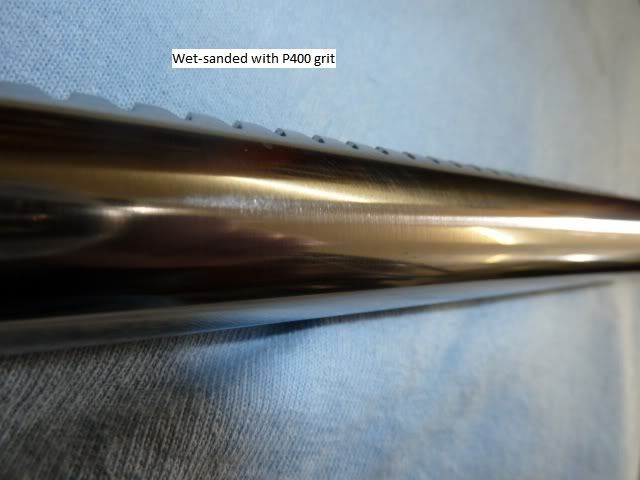
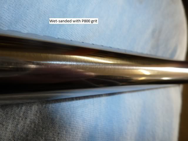
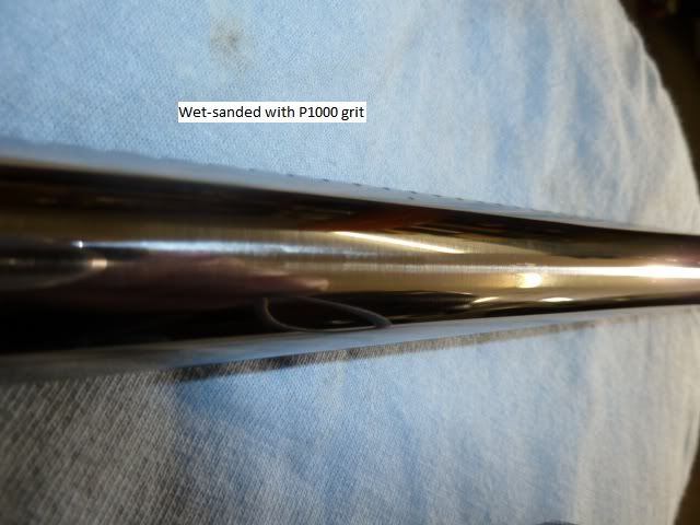
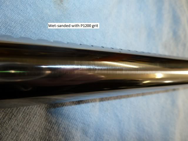
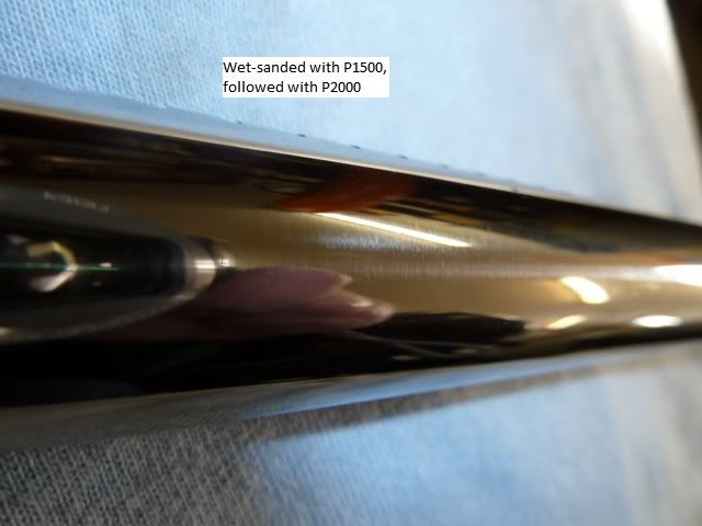
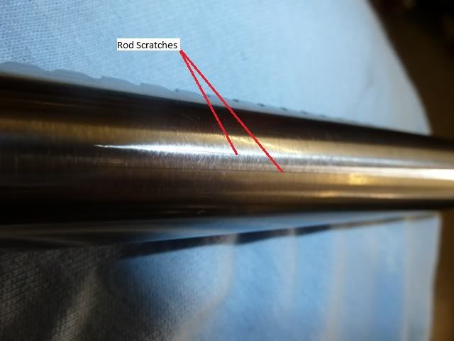
Begin sanding so that the sanding marks are circumferential, as linear scratches can cause problems. Move slowly along the length, between piston and vent hole, stopping occasionally to clean the sandpaper with the water mix. Index to 2, repeat sanding, etc. Try to spend the same amount of time at each indexing to prevent an out-of-round rod. Use a cotton towel (t-shirt) to wipe clean. If the linear scratches are gone, switch to 800 grit and repeat the technique. Continue with the technique until finished with 1200 grit. At this point, the finish should be shiny with only tiny circumferential scratches. If you’re detail oriented, feel free to sand with 1500 and 2000. You’ll end up with a mirror finish as shown in the pic.
Approximate surface finish relative to wet sandpaper:
• P400 = 35 micron
• P800 = 22
• P1000 = 18
• P1200 =15
Piston Seal Installation:
You can replace this if you want to, but unless it has obvious damage it’s not necessary. The Teflon seal I removed from a 277k mile rack had less than .001” wear. If you insist on replacing the seal, be cautious not to cut the o-ring that is underneath it. A new o-ring is not supplied in the Subaru kit. Also, any burrs caused by seal removal must be filed or sanded smooth to prevent scarring the cylinder bore.
Rack Installation:
Before installing the rack, you will need to slip the new LH seal over the rack teeth and up against the piston. Obviously, the rack teeth will tear the seal lip to shreds unless we use a special tool. Fear not, we have our own special tool, 3/4" masking tape. We will be applying tape over all sharp edges that could slice our new seal including the wrench flats at the ends of the rack. First, apply two strips of tape lengthwise down the rack teeth and wrap over the end of the rack covering those wrench flats. Next, tape the other end of the rack. On this end, there is a step down of about .020". Tape circumferentially, so that the edge of the tape is flush against this step. Add another piece so that it will overlap the wrench flats when folded in.
Apply a light coat of moly grease to the rod and taped areas, the OD of the rod piston, OD & ID of the LH rod seal and OD of backup washer. Slide and rotate the rod seal over the taped rod until flush with the piston. Not that the garter spring side of the seal MUST face the piston, while the built-in nylon bushing faces outward. Slide the retaining washer up against the seal, cupped portion of washer MUST face away from seal.
Apply a coat of grease to the seal gland OD & O-ring, seal ID and gland ID. Slide and rotate the rod seal over the taped rod end until flush with the piston. Again, the garter spring side of the seal faces the piston, while the bushing portion of the seal faces away from the piston. Remove all tape.
Liberally apply grease to the rack teeth, housing pinion area, and the rack bore. Stand the rack housing on end and carefully lower the rack assembly into the housing. Move the housing to the edge of the bench so the rack end can protrude. Ensure the seal gland is fully seated as the o-ring will tend to hang-up. Using a soft punch (brass, wood, etc.) and dead-blow hammer, tap on the end of the rack until the backup washer and LH seal are fully seated. This doesn’t take much force, especially if you remembered to grease the OD of the washer and seal.
Make sure no burrs were raised on the end of the rod, and then install the retaining gland. Install the lockwire using the same technique used to remove it.
Coat the pinion teeth and pack the pinion bearing with grease, slip the shim over the bearing, then install the assembly into the rack housing. Tighten the two screws and reattach the four hydraulic lines.
Install the backlash adjustment sleeve, spring and screw. Rotate the pinion shaft by hand so that the rack is moved completely to the left. Tighten the adjustment sleeve screw to 10 ft-lb or so, then loosen it 1/16 of a turn or roughly 22.5 degrees. This allows the spring to keep the proper amount of pressure on the rack. BE WARNED, if there was sleeve wear on the rack, then that area is lower. This is why the sleeve pressure must be set on an un-worn area of the rack by moving the rack all the way to the left. Get it? Verify you got it right by turning the rack full right and left while checking for binding.
At this point, it would be a good idea to inspect the inner tie-rods for wear. If there is any movement in the ball and socket, it must be replaced. However, inner tie-rods seldom go bad. Clean the ball and socket with kerosene, and then blow dry with compressed air. Pack the ball and socket with moly grease and it is ready to be reinstalled.
Install the RH boot spacer, then reattach inner tie-rods making sure these are torqued adequately. Secure the connection using a punch to peen the lockwasher. Slide the boots onto the rack housing and retain with the garter springs.
Reinstall the rack to the vehicle. With the steering wheel in the locked position, move the rack until the steering knuckle measurement recorded earlier is attained. Slide the steering column u-joint coupling onto the rack pinion splines and tighten all hardware. This might take a couple of attempts to get it right. I left the LH steering rack bushing cap loose to allow the rack to drop down enough to slide the coupling on the pinion. Then by hand, I held the end of the rack in place and measured until it was on the money.
Bleeding the System:
Add Dexron 3 to the reservoir, then rotate the rack full left and right a few times. Re-fill the reservoir, then start the car. Add more fluid as the pump reservoir will quickly run dry. Use the steering wheel to turn full left, then right a few more times. Turn the motor off as your pump should be making a lot of noise (cavitation) due to air in the oil. Wait a few moments until the bubbles in the pump reservoir go away, then add more oil. With the engine off, turn full left and right, then start the car and repeat left then right until the reservoir level stabilizes without bubbles. This method will help prevent cavitation damage and quickly bleed the system of air.
That’s it! You’re done and you didn’t even lose your alignment!
Additional Technical Info:
• Rack is induction hardened, Rc 56
• New Rod OD = 0.9445” or half thousandths under 24mm
• Cylinder ID approximately = 41mm or 1.61”
• Piston area = 1.34 in^2
• Tie-rod push at pump relief = 1238 lbf NA; 1430 lbf turbo
• Rack length = 611.5mm or 24.075”
• Backup Washer ID = 0.965”
• Seal Gland Bushing ID = 0.950”
• Subaru cylinder bore is steel, low quality cars are aluminum which wears quickly.
• RH leak can travel to LH through the vent holes.
• A steel wool filter inside both cylinder pressure ports protects pump from rack contamination.
Why would you want to fix your own rack when a rebuilt is available for $160? Well, as Gump says, “you never know what you’re gonna get”. Racks are usually extremely worn out when they are sent to the core rebuilder. So, you may be receiving a rack in worse condition than the one you sent in. Yes, remanufacturers do grind the seal areas of the rack, but these may be ground grossly undersize. Furthermore, there is nothing they can do about worn pinion or rack teeth, at least not for $160. They will also use the cheapest seals, boots and tie-rods they can find. That means your gamble will be inferior to a repair using these instructions, OE seals and boots. Your cost to do it right the first time is: seal kit $40, boots $48, sandpaper $15….
Required Tools:
• 12mm socket and ratchet
• 14mm wrench
• 17mm wrench
• 19mm wrench
• Large Crescent wrench (30mm opening)
• Small flat-tipped screwdriver (1/8” wide)
• 1/8” punch
• Hammer (dead-blow preferred)
Required Materials:
• Kerosene
• Moly grease (STA-Lube Disc Brake Grease works well: http://www.crcindustries.com/auto/conte ... SL3161&S=N)
• One sheet each of 3M wet sandpaper in 400, 800, 1000 and 1200 grit: http://solutions.3m.com/wps/portal/3M/e ... 0CVBK1Q8gl
• Permanent marker
• 3/4” masking tape
• Razor blade
• Subaru output seal kit P/N 34128AA211, ’90-’94 Legacy
Shop Time:
This repair requires that you remove, tear-down, clean twice, refinish, reassebmle and then install a power steering rack. If I had all the parts on hand, I could easily do it in a weekend (8 hours). Plan accordingly, as your your ride could be down for a few days.
Alignment Preservation:
Straighten the steering wheel and let the steering lock in the nearest position. Remove the tires and record a measurement from the steering knuckle to the body. Try to keep this measurement parallel with the rack for accuracy and repeatability. This measurement will be used to align the steering wheel to the rack and pinion. Remove the rack from the car, complete with outer tie rod ends to preserve alignment. Take to car wash and steam clean. Try not to get water in the two open hydraulic pressure and return lines.
Inner Tie-Rod Removal:
Flip up the large end of the rack boots, exposing a spring garter. Move the garter away from the rack housing and pull the boot free from the housing. To gain access to the inner tie rod connection, roll the boot back on itself, exposing the tie rod lock washer. Place a 19mm open end wrench onto the rack wrench flats, then hammer out the lock washer indentions using a small diameter punch. Place a large crescent wrench on the inner tie rod flats, and with the 19mm wrench against the bench top, hit the crescent wrench with a dead blow hammer knocking the tie rod threads loose. Note that all threads are RH threads “righty-tighty, lefty-loosey”. At this point, the tie-rod can be unscrewed by hand. Repeat process to remove opposite tie-rod.
Backlash Adjustment Sleeve Removal:
This sleeve presses the rack against the pinion teeth. Loosen the 30mm locknut with a big crescent and dead-blow hammer. Use a 14mm socket to remove the adjusting screw. Turn housing over and dump out the spring and adjustment sleeve.
Pinion Assembly Removal:
Before the rack can be removed, the drive gear or “pinion” has to come out. Loosen all four hydraulic lines from the input housing, and then remove the two pinion housing screws. With a few wiggles, the pinion assembly will pull straight out of the rack housing. Note the gasket between the pinion assembly and main housing. It is a shim used to set the depth between the pinion bearing and the rack housing and will be replaced with a new shim. The old shim can be removed using a razor-blade at a slight angle.
The pinion assembly will not be resealed as these seals usually don’t leak. The pinion, unlike the rack, experiences only rotational motion and is not subject to high contamination or heat. Clean the pinion teeth and ball bearing, and set the assembly aside.
Retaining Gland Removal:
The rack assembly is held together with a lockwire that is removed through a slot at one end of the housing. To remove the lockwire, first expose its end by turning the retaining gland. The gland turns easily using light taps against the lugs on its end. When the end of the wire is visible, lift using a small screwdriver, and then again turn the retaining gland. This will cause the wire to climb out of the slot and unwind from the housing. The last part of the wire is a 90 degree tang that fits into a hole in the gland. Just lift it straight out. A new lockwire is supplied in the repair kit.
Rack/Rod Removal:
Pull and turn the rack at the same time, to help the teeth move past the LH seal. Be careful not to let the end of the rack drop down inside housing, as this could cause a scratch in the housing cylinder. With the components removed, you will probably find a portion of the seal gland to be rusty. A new one complete with seal and o-ring is supplied in the repair kit.
LH or Inner Seal Removal:
The inner seal is pressed in and will have to be tapped out. Stand the housing assembly on end, with the aluminum portion facing up. Next, insert a socket with a diameter just small enough to slide into the bore of the aluminum housing. Insert the handle of a half-inch drive breaker bar into the bore and against the socket, then tap on the end of the handle until the seal pops loose. Examine the parts that just came out. One will be a freeze plug looking thing called the seal backup washer. Its job is to prevent the seal bushing from popping out under hydraulic pressure. As such, the inner diameter is close tolerance to the OD of the rod.
Final Cleaning:
Take the housing back to the car wash and blast away any remaining grease. Note that there is a needle bearing in the pinion area. After washing, dry the water from the bearing using a paper towel, and apply a coat of moly grease to the needles. Then, carefully dry the cylinder bore using paper towels and a plastic or wooden handle to move the towels through the bore.
Pour some kerosene into a coffee can and clean up all the little parts, then blow dry with compressed air and set aside on a paper towel.
Parts Inspection:
Inspect the cylinder bore to make sure it is smooth with no dents or deep scratches. Shallow scratches won’t hurt anything. Sure, the piston slides and seals against the cylinder wall, but if it leaks from one side of the piston to the other, it just takes away some efficiency of the power assist. However, it will not cause a leak outside of the rack.
Check the inner diameter of the backup washer for burrs caused by the removal process. If any exist, these must be removed with a file or sandpaper. The ID is only .020” larger than the rod, so it has to be burr free.
Slop in the steering is caused by excessive wear of rack and pinion teeth. Since 90% of a steering wheel’s life is pointing straight ahead, tooth wear will only be found on the center of rack. Same thing for the pinion, only a couple of teeth will be heavily worn. The good news is that the pinion can be turned so that when reassembled, wear free pinion teeth are in contact with the worn part of the rack thereby reducing steering slop.
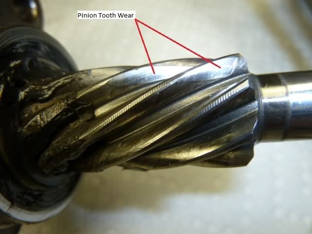
The rod portion of the rack is the most important. It should be inspected for radial erosion and linear scratches in between the piston and the vent holes. Also of concern is wear at the backlash adjustment sleeve contact point. This type of damage may be sanded out but must follow proper technique.
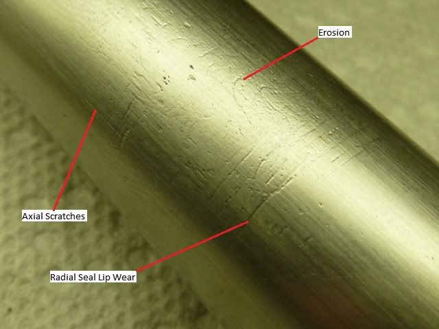
Rod Re-finishing:
This is imperative to eliminate leaks! The rod is to be re-finished using 3M wet sandpaper in grits: 400, 800, 1000, and 1200. If you are using full-sheets, cut these into thirds. If using half-sheets, cut in half. Begin by measuring the rod diameter using a caliper (it doesn’t need to be calibrated or accurate). Record this dimension as you will be comparing your final sanded diameter to make sure it is not too small or out-of-round. The seals should tolerate up to 0.003” of rod reduction and 0.001” of out-of-round, although I doubt anyone would take that much off using this home-brew method. Next, mark “1, 2, 3” equally spaced around each end of the rack. You will use these marks to index the rod 120 degrees in between sandings, thereby preventing an out-of-round condition.
Mix dishwashing soap and water in a large bowl. Find something low to sit on (I used a milk crate), then place a towel or throw blanket on the seat. Now, place one end of the rod on the towel with the 1 mark indexed up and sit on the rack. The towel will prevent damage to the finish. Put the bowl of soapy water under the overhanging portion of the rod then wrap the sandpaper around it.
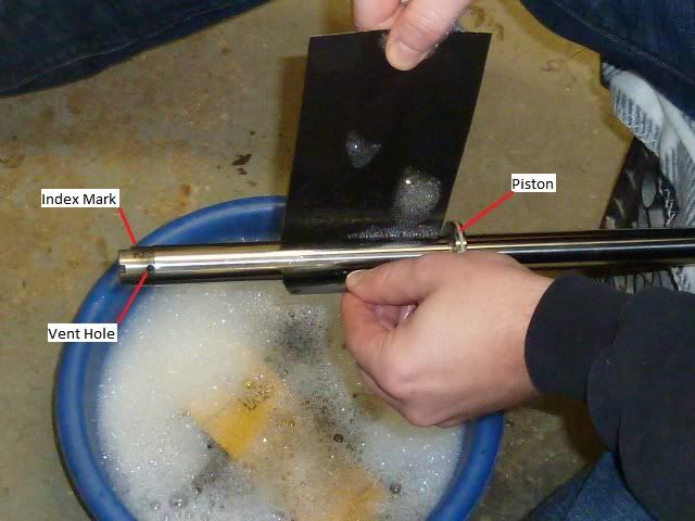
Begin sanding so that the sanding marks are circumferential, as linear scratches can cause problems. Move slowly along the length, between piston and vent hole, stopping occasionally to clean the sandpaper with the water mix. Index to 2, repeat sanding, etc. Try to spend the same amount of time at each indexing to prevent an out-of-round rod. Use a cotton towel (t-shirt) to wipe clean. If the linear scratches are gone, switch to 800 grit and repeat the technique. Continue with the technique until finished with 1200 grit. At this point, the finish should be shiny with only tiny circumferential scratches. If you’re detail oriented, feel free to sand with 1500 and 2000. You’ll end up with a mirror finish as shown in the pic.
Approximate surface finish relative to wet sandpaper:
• P400 = 35 micron
• P800 = 22
• P1000 = 18
• P1200 =15
Piston Seal Installation:
You can replace this if you want to, but unless it has obvious damage it’s not necessary. The Teflon seal I removed from a 277k mile rack had less than .001” wear. If you insist on replacing the seal, be cautious not to cut the o-ring that is underneath it. A new o-ring is not supplied in the Subaru kit. Also, any burrs caused by seal removal must be filed or sanded smooth to prevent scarring the cylinder bore.
Rack Installation:
Before installing the rack, you will need to slip the new LH seal over the rack teeth and up against the piston. Obviously, the rack teeth will tear the seal lip to shreds unless we use a special tool. Fear not, we have our own special tool, 3/4" masking tape. We will be applying tape over all sharp edges that could slice our new seal including the wrench flats at the ends of the rack. First, apply two strips of tape lengthwise down the rack teeth and wrap over the end of the rack covering those wrench flats. Next, tape the other end of the rack. On this end, there is a step down of about .020". Tape circumferentially, so that the edge of the tape is flush against this step. Add another piece so that it will overlap the wrench flats when folded in.
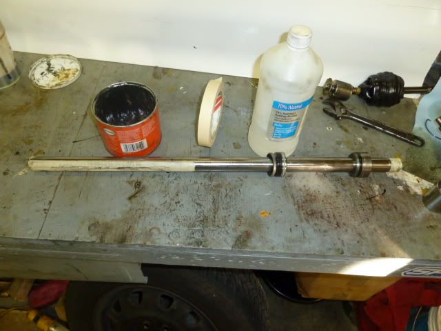
Apply a light coat of moly grease to the rod and taped areas, the OD of the rod piston, OD & ID of the LH rod seal and OD of backup washer. Slide and rotate the rod seal over the taped rod until flush with the piston. Not that the garter spring side of the seal MUST face the piston, while the built-in nylon bushing faces outward. Slide the retaining washer up against the seal, cupped portion of washer MUST face away from seal.
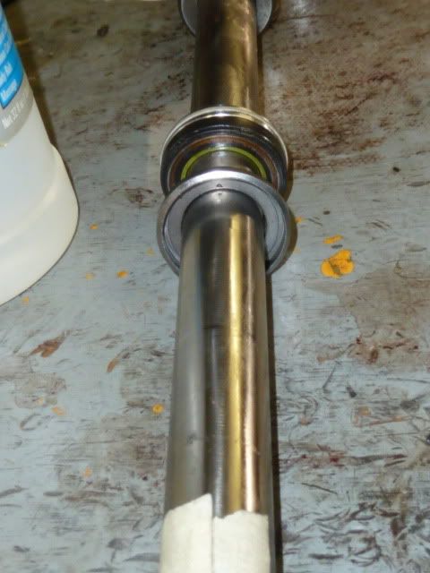
Apply a coat of grease to the seal gland OD & O-ring, seal ID and gland ID. Slide and rotate the rod seal over the taped rod end until flush with the piston. Again, the garter spring side of the seal faces the piston, while the bushing portion of the seal faces away from the piston. Remove all tape.
Liberally apply grease to the rack teeth, housing pinion area, and the rack bore. Stand the rack housing on end and carefully lower the rack assembly into the housing. Move the housing to the edge of the bench so the rack end can protrude. Ensure the seal gland is fully seated as the o-ring will tend to hang-up. Using a soft punch (brass, wood, etc.) and dead-blow hammer, tap on the end of the rack until the backup washer and LH seal are fully seated. This doesn’t take much force, especially if you remembered to grease the OD of the washer and seal.
Make sure no burrs were raised on the end of the rod, and then install the retaining gland. Install the lockwire using the same technique used to remove it.
Coat the pinion teeth and pack the pinion bearing with grease, slip the shim over the bearing, then install the assembly into the rack housing. Tighten the two screws and reattach the four hydraulic lines.
Install the backlash adjustment sleeve, spring and screw. Rotate the pinion shaft by hand so that the rack is moved completely to the left. Tighten the adjustment sleeve screw to 10 ft-lb or so, then loosen it 1/16 of a turn or roughly 22.5 degrees. This allows the spring to keep the proper amount of pressure on the rack. BE WARNED, if there was sleeve wear on the rack, then that area is lower. This is why the sleeve pressure must be set on an un-worn area of the rack by moving the rack all the way to the left. Get it? Verify you got it right by turning the rack full right and left while checking for binding.
At this point, it would be a good idea to inspect the inner tie-rods for wear. If there is any movement in the ball and socket, it must be replaced. However, inner tie-rods seldom go bad. Clean the ball and socket with kerosene, and then blow dry with compressed air. Pack the ball and socket with moly grease and it is ready to be reinstalled.
Install the RH boot spacer, then reattach inner tie-rods making sure these are torqued adequately. Secure the connection using a punch to peen the lockwasher. Slide the boots onto the rack housing and retain with the garter springs.
Reinstall the rack to the vehicle. With the steering wheel in the locked position, move the rack until the steering knuckle measurement recorded earlier is attained. Slide the steering column u-joint coupling onto the rack pinion splines and tighten all hardware. This might take a couple of attempts to get it right. I left the LH steering rack bushing cap loose to allow the rack to drop down enough to slide the coupling on the pinion. Then by hand, I held the end of the rack in place and measured until it was on the money.
Bleeding the System:
Add Dexron 3 to the reservoir, then rotate the rack full left and right a few times. Re-fill the reservoir, then start the car. Add more fluid as the pump reservoir will quickly run dry. Use the steering wheel to turn full left, then right a few more times. Turn the motor off as your pump should be making a lot of noise (cavitation) due to air in the oil. Wait a few moments until the bubbles in the pump reservoir go away, then add more oil. With the engine off, turn full left and right, then start the car and repeat left then right until the reservoir level stabilizes without bubbles. This method will help prevent cavitation damage and quickly bleed the system of air.
That’s it! You’re done and you didn’t even lose your alignment!
Additional Technical Info:
• Rack is induction hardened, Rc 56
• New Rod OD = 0.9445” or half thousandths under 24mm
• Cylinder ID approximately = 41mm or 1.61”
• Piston area = 1.34 in^2
• Tie-rod push at pump relief = 1238 lbf NA; 1430 lbf turbo
• Rack length = 611.5mm or 24.075”
• Backup Washer ID = 0.965”
• Seal Gland Bushing ID = 0.950”
• Subaru cylinder bore is steel, low quality cars are aluminum which wears quickly.
• RH leak can travel to LH through the vent holes.
• A steel wool filter inside both cylinder pressure ports protects pump from rack contamination.
Last edited by bry on Fri Dec 24, 2010 7:47 pm, edited 15 times in total.
Re: How to Repair a Leaking Steering rack: Subaru Legacy, '9
Very nice write-up
Josh
surrealmirage.com/subaru
1990 Legacy (AWD, 6MT, & EJ22T Swap)
2020 Outback Limted XT
If you need to get a hold of me please email me rather then pm
surrealmirage.com/subaru
1990 Legacy (AWD, 6MT, & EJ22T Swap)
2020 Outback Limted XT
If you need to get a hold of me please email me rather then pm
Re: How to Repair a Leaking Steering rack: Subaru Legacy, '9
I'll have tO read more in the morning as I got my spare rack and a reseal kit waitingto be used. Great write up.
-04 WRX STi - Java Black Pearl - Cobb Stage 2
-02 Forester Type S premium - Platinum Silver Metallic - Stock
-92 Legacy Sport Sedan - Onyx Black Pearl - Stock
-02 Forester Type S premium - Platinum Silver Metallic - Stock
-92 Legacy Sport Sedan - Onyx Black Pearl - Stock
-
- Fifth Gear
- Posts: 2774
- Joined: Sun Nov 23, 2003 12:22 am
- Location: Western WA!
Re: How to Repair a Leaking Steering rack: Subaru Legacy, '9
AWESOME write-up! THANKS for taking the time and pics for the detailed explanation and instructions!
'94 TW
Re: How to Repair a Leaking Steering rack: Subaru Legacy, '9
Thanks for doing this great write up. Will do this on the '94. There are many good repair articles in this forum, but this one is maybe the best. The text and pictures are just, over the top.
Re: How to Repair a Leaking Steering rack: Subaru Legacy, '9
Appreciate it! It did take a bit of time to put this together, but it is a useful addition to the forum. It's rare to find an early Subaru without rack leaks and there is very little info on the net regarding proper repair of any make of rack.
Just so you know, I used two 1990 racks for this write-up. The one I repaired came from a 277K mile salvage car that still had fairly good boots. The damage pics are from a 150k mile rack that had been driven with disintegrated boots for a long time. It was so bad, the power steering reservoir would empty in a week, even without being driven. This rack could have been repaired, but I prefer to start with a better core if possible. The 277K mile core cost me $25 at a pick-a-part.
Re: How to Repair a Leaking Steering rack: Subaru Legacy, '9
Thanks man for doin this. This is he best write ip ive seen so far.. Pretty much idiot proof. Im gonna be doin this to mine pretty soon. Mines got 297k on it but the boots are still in good shape. Just that one leak on the passengers side like i said in my post before. I realy appreciate this man, helps me from tryin to figure out which racks will work on my 90 and chancing on getting a bad one from the junkyard. This didnt take you too long at all from when u said u were gonna do it on my post. Two thumbs up man. This forum is just full of awsome people with awsome knowlege of these cars, thanks for sharing it.
90 2.2 N/A legacy awd wagon with outback struts.
Re: How to Repair a Leaking Steering rack: Subaru Legacy, '9
Hey Shag,
Sounds like your rack is a good candidate for this repair. If it is anything like mine, you'll have to take only .001" off the rod diameter to restore the finish. This will be way better than what you would have in a low-buck remanufactured unit.
-bry
Sounds like your rack is a good candidate for this repair. If it is anything like mine, you'll have to take only .001" off the rod diameter to restore the finish. This will be way better than what you would have in a low-buck remanufactured unit.
-bry
-
- Second Gear
- Posts: 342
- Joined: Sat Aug 07, 2004 9:29 am
- Location: Jackson County OR
- Contact:
Re: How to Repair a Leaking Steering rack: Subaru Legacy, '9
Sticky!
Robert,
Rio Red 1990 L sedan 5MT at least 302000 mi. and Spruce Pearl 1996 Wagon 4EAT 245000 mi.
georryan wrote:
Don't knock him for thinking outside of the box. At least he has been creative.
Rio Red 1990 L sedan 5MT at least 302000 mi. and Spruce Pearl 1996 Wagon 4EAT 245000 mi.
georryan wrote:
Don't knock him for thinking outside of the box. At least he has been creative.
Re: How to Repair a Leaking Steering rack: Subaru Legacy, '9
I second the sticky!
90 2.2 N/A legacy awd wagon with outback struts.
Re: How to Repair a Leaking Steering rack: Subaru Legacy, '9
It already is a sticky. Josh put it there soon after it was posted.
-
- Fifth Gear
- Posts: 8360
- Joined: Mon Nov 06, 2006 3:41 am
- Location: Tenino, WA
Re: How to Repair a Leaking Steering rack: Subaru Legacy, '9
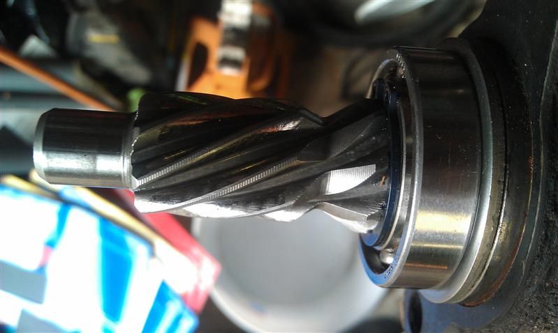
I noticed when I disassembled my rack today that my pinion gear looks different than the one in the picture in this write-up. Mine has a large dip in the teeth on the inside. Is this normal? What's the purpose of the drip in the teeth? It has the little groove pattern on it still (would be smooth if it was wear) can't be worn down like that which I initially thought.
98 Metro Hatch Daily Driver :)
91 SS EJ20G Engine/Tranny/Diff Swap Build Thread Here
"Your testes are close to your bottom but you still play with them all the time." Jeremy Clarkson
91 SS EJ20G Engine/Tranny/Diff Swap Build Thread Here
"Your testes are close to your bottom but you still play with them all the time." Jeremy Clarkson
Re: How to Repair a Leaking Steering rack: Subaru Legacy, '9
You can kind of see in one of the pics above where there's a little dip towards the back. I couldn't tell you whether this is wear or just normal. Hopefully bry and others can reply with their thoughts.
Josh
surrealmirage.com/subaru
1990 Legacy (AWD, 6MT, & EJ22T Swap)
2020 Outback Limted XT
If you need to get a hold of me please email me rather then pm
surrealmirage.com/subaru
1990 Legacy (AWD, 6MT, & EJ22T Swap)
2020 Outback Limted XT
If you need to get a hold of me please email me rather then pm
Re: How to Repair a Leaking Steering rack: Subaru Legacy, '9
couldn't you get another steering rack from an impreza or wrx and it would work? or is that part not interchangeable
-
- Fifth Gear
- Posts: 8360
- Joined: Mon Nov 06, 2006 3:41 am
- Location: Tenino, WA
Re: How to Repair a Leaking Steering rack: Subaru Legacy, '9
You can do that but youll be going to a slightly slower ratio rack since the turbo legacy had the fastest rack IIRC. I wanted to do this to keep my rack and know for sure it wasnt going to leak and it would last a long time.
98 Metro Hatch Daily Driver :)
91 SS EJ20G Engine/Tranny/Diff Swap Build Thread Here
"Your testes are close to your bottom but you still play with them all the time." Jeremy Clarkson
91 SS EJ20G Engine/Tranny/Diff Swap Build Thread Here
"Your testes are close to your bottom but you still play with them all the time." Jeremy Clarkson
Re: How to Repair a Leaking Steering rack: Subaru Legacy, '9
good to know, I wasn't being a douche just trying to decide on what I want to do with mine since it is leaking...
Re: How to Repair a Leaking Steering rack: Subaru Legacy, '9
Hmm....maybe I need to find a turbo legacy rack. I didn't know they were the fastest.
Josh
surrealmirage.com/subaru
1990 Legacy (AWD, 6MT, & EJ22T Swap)
2020 Outback Limted XT
If you need to get a hold of me please email me rather then pm
surrealmirage.com/subaru
1990 Legacy (AWD, 6MT, & EJ22T Swap)
2020 Outback Limted XT
If you need to get a hold of me please email me rather then pm
-
- Fifth Gear
- Posts: 8360
- Joined: Mon Nov 06, 2006 3:41 am
- Location: Tenino, WA
Re: How to Repair a Leaking Steering rack: Subaru Legacy, '9
I read it on here a long time ago but I don't know what thread it was from.
98 Metro Hatch Daily Driver :)
91 SS EJ20G Engine/Tranny/Diff Swap Build Thread Here
"Your testes are close to your bottom but you still play with them all the time." Jeremy Clarkson
91 SS EJ20G Engine/Tranny/Diff Swap Build Thread Here
"Your testes are close to your bottom but you still play with them all the time." Jeremy Clarkson
Re: How to Repair a Leaking Steering rack: Subaru Legacy, '9
The wrx and sti racks need modifications done to them or they won't fit.reecers wrote:couldn't you get another steering rack from an impreza or wrx and it would work? or is that part not interchangeable
And from what I remember, the first gen turbo steering racks had the quickest rates of all Subies made, at least up to 2005.
A bit off-topic, but: For even quicker rates, there are at least two companies (the last I checked a few years ago) that make quick-steering kits for Subarus. Of course, the OEM steering rack will have to be modified but you can get ratios down to 12:1 or less. Some years back, I used to live in a place where I had to negotiate over 900 curves in a two-hour drive. I drove that road at least twice a week. The quick-steering kit I had on my car really made that drive enjoyable. I rarely had to lift my hands off the steering wheel to negotiate a turn or curve. From what I recall, from center to either left or right lock, it was about 3/4 turn of the steering wheel. I don't recall what the steering ratio was, but I wish my Leggies had that steering ratio.
'94 TW
Re: How to Repair a Leaking Steering rack: Subaru Legacy, '9
Where the rack's teeth meets the pinion housing assembly gear, does this need to be grease packed? Reason I ask is that there is a bearing behind the pinion gear and wondered if its lubricated by bearing grease.
-04 WRX STi - Java Black Pearl - Cobb Stage 2
-02 Forester Type S premium - Platinum Silver Metallic - Stock
-92 Legacy Sport Sedan - Onyx Black Pearl - Stock
-02 Forester Type S premium - Platinum Silver Metallic - Stock
-92 Legacy Sport Sedan - Onyx Black Pearl - Stock
Re: How to Repair a Leaking Steering rack: Subaru Legacy, '9
Recently did a steering rack rebuild using the pictured write up above. For adjusting the backlash of the rack and pinion, if you tighten the adjusting screw to 10 ft.-lbs., it will be bound up. Per the factory Service Manual, the proper procedure is:
1. Tighten adjusting screw to 3.6 ft-lbs(43 in-lbs) and then loosen. Repeat this operation twice.
2. Retighten adjusting screw to 3.6 ft-lbs and back off 30*.
3. Apply liquid packing(Locktite) to at least 1/3 of entire perimeter of adjusting screw thread.[On top]
4. Install lock nut. a. While holding adjusting screw with a wrench to prevent it from turning, tighten lock nut
to 22-36 ft-lbs. b. Make adjustment so that rack can be moved from lock to lock without binding.
The key is to back off the adjusting screw, after tightening it to 3.6 ft-lbs, so the rack moves freely from lock to lock without binding, 30* appears to be a approx. number.
Worked for me, may help others.
Also replaced the piston seal with the new one from the kit, not hard to do, for sure be aware of the rubber o-ring beneath it when removing the old one.
Re: How to Repair a Leaking Steering rack: Subaru Legacy, '9
I guess you've got to get a small torque wrench to measure 3.6 ft-lbs.
BTW, I fixed your units. It's ft-lbs not ft/lbs
Josh
surrealmirage.com/subaru
1990 Legacy (AWD, 6MT, & EJ22T Swap)
2020 Outback Limted XT
If you need to get a hold of me please email me rather then pm
surrealmirage.com/subaru
1990 Legacy (AWD, 6MT, & EJ22T Swap)
2020 Outback Limted XT
If you need to get a hold of me please email me rather then pm
-
- Fifth Gear
- Posts: 8360
- Joined: Mon Nov 06, 2006 3:41 am
- Location: Tenino, WA
Re: How to Repair a Leaking Steering rack: Subaru Legacy, '9
I've got a small 1/4" inch-lb torque wrench I converted the units to inches and used that.
98 Metro Hatch Daily Driver :)
91 SS EJ20G Engine/Tranny/Diff Swap Build Thread Here
"Your testes are close to your bottom but you still play with them all the time." Jeremy Clarkson
91 SS EJ20G Engine/Tranny/Diff Swap Build Thread Here
"Your testes are close to your bottom but you still play with them all the time." Jeremy Clarkson
Re: How to Repair a Leaking Steering rack: Subaru Legacy, '9
English majors/engineers--Good shop practice has you convert to in-lbs to get into a usable range to select your torque wrench. There are guidelines for selecting what tw to use.
When applying torque, torque wrenches shall be selected for the job such that the final applied torque value of the assembly is between 20% and 90% of the full scale (maximum capacity) of the torque wrench.
Example: A 15 to 75 ft-lb torque wrench would be acceptable for torque values between 15 ft-lb (i.e. 20%, .2 x 75 ft-lbs) and 67.5 ft-lbs (i.e. 90%, .9 x 75 ft-lbs).
Kimo, you passed.
Class dismissed.