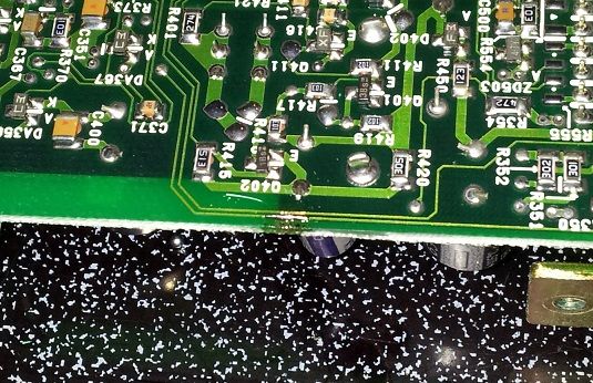
So, back in April I mailed out an EJ20G ECU to Rob Files to have his chip installed. In transit, the board rubbed against one of the tabs of the ECU case (the case was taken apart and the board stuck into the top part to facilitate fitment into a small flat-rate box), resulting in a broken trace on the edge of the board. Oh nos! The damage resulted in an ECU that throws codes for the MAP sensor and TPS and runs in limp mode. Luckily I had another EJ20G ECU on-hand to verify that this behavior was due to the ECU and not the MAP/TPS.
Rob was more than happy to swap out the chip for me into another ECU free of charge. However, I really didn't want to wait two weeks to drive my car that I had just got running. So, I popped her open and decided to see what the harm could be in trying to simply reconnect the broken copper trace, since the ECU board was going in the trash otherwise.
These photos here are reproductions of the damage and repair with a '92 N/A Legacy ECU board, but it looks identical to the EJ20G board (identical enough that Rob actually played with using his tune on the 92-94 N/A ECU, though internal signaling differences have at least temporarily shelved that idea).
These photos were also taken over a very bad photographing surface, my ceramic stovetop. It's perfect for soldering as no soldering tool gets anywhere close to hot enough to damage it. But it's also got a lot of reflective white dots in the finish that my cellphone camera doesn't know what to do with, causing none of the pictures to appear 100% focused (with or without flash).
Here's the tools I used:
-25W Soldering Iron
-.022" Rosin-Core Silver-Bearing Solder
-Very small flat screwdriver
-Razor blade
-16awg primary wire (any stranded copper wire should work)
--Thinking back, tweezers would have helped immensely.
--Reading glasses would have helped a lot too.
Note: It took me the better part of 40 minutes to do this. If you don't have your 2 year old daughter climbing on your back the whole time, it should be significantly faster.
Here's the initial damage. Only the outer-most trace is actually broken, the inner trace that's scraped still works fine. Firstly you will want to ensure there is bare copper on either side of the break that you can solder to. A small screwdriver or razor rubbed GENTLY over the trace will scrape away the circuit board resin and expose the copper.

We will start by melting a smallish glob of solder onto the area to be repaired. This deposits a layer of flux, which will provide some tack for later on, as well as doing whatever else it is that flux does. Like I said, I'm not soldering expert

Use the soldering iron to just push the solder off the side of the board. It won't stick to anything at this point. As you can see, there is a nice goopy deposit all over the repair area.

Now we will snip off a tiny strand of copper wire. This is what's gonna be soldered over the broken trace.

Place the wire over the break, making sure it's just the right length to lay on the exposed copper ends of the broken trace.

Now we attempt to solder that little wire. This part is what really takes some patience, a steady breathing rate, and more patience. You will almost definitely get way too much solder on there. You'll probably have to try and push excess solder off the side. On this repair specifically, this is very important because we have an exposed trace roughly 1mm away from the repair. You just want enough that the wire and the ends of the traces are silver with solder. I'm sure there's a cleaner way to do this, but as I mentioned this is demonstrating how someone with little soldering knowledge and is in a rush to drive their car again can perform a working fix without blowing up their car (that said, I'm not responsible if anything gets fried or blows up as a result of trying this

All finished. Throw it in and test it out. Worst case scenario is that you just wasted 10-30 minutes and still have a junk ECU board. In my case the CEL went away, and now I get to enjoy my Rob Tune without limp mode!

If you're like me, then you probably considered just laying a bead of solder across the trace. Upon seeing that it just globs up and rolls off leaving flux behind, you'll come to your senses and solder a copper wire on there like you're supposed to.


